Francesco Prati, Flavio Giuseppe Biccirè
Stents and scaffolds
Updated on May 13, 2021
Both the guide catheter and the guidewire are essential tools for percutaneous coronary intervention (PCI). Understanding the construction, design features and performance characteristics will facilitate their appropriate selection. A good guide catheter provides coaxial alignment for contrast injection and smooth delivery of the device to the target site. Guide catheters of various sizes and shapes are selected based on vessel anatomy, lesion characteristics, vascular access and procedural complexity. Similarly, guidewire selection is tailored to specific lesion characteristics. As more challenging lesions are attempted percutaneously, improved guidewire technology and their better understanding assume greater importance. Both the guide catheter and the guidewire need to be manipulated with care to avoid iatrogenic complications. Their historical development, present status and future direction are reviewed here.
Besides serving as a conduit for contrast delivery and pressure measurement, an “ideal” guide catheter provides coaxial alignment and support for device passage and advancement to the target site. Compared to diagnostic catheters, guide catheters have a stiffer shaft, larger lumen diameter, and a shorter, non-tapered and less angulated tip (Table GC 1). Catheter tips are usually radiopaque and soft, allowing less traumatic engagement of the vessel ostium. Guide catheters are available in a variety of shapes and sizes to suit different patient anatomies and lesion types. Various anatomic and procedural factors need to be considered in selecting guide catheters (Table GC 2). These factors include the size of the aortic root, aortic arch configuration, coronary/graft anatomy (ostium location and vessel orientation), access site (TFI vs. TRI, right vs. left), body habitus, and the need for catheter support.
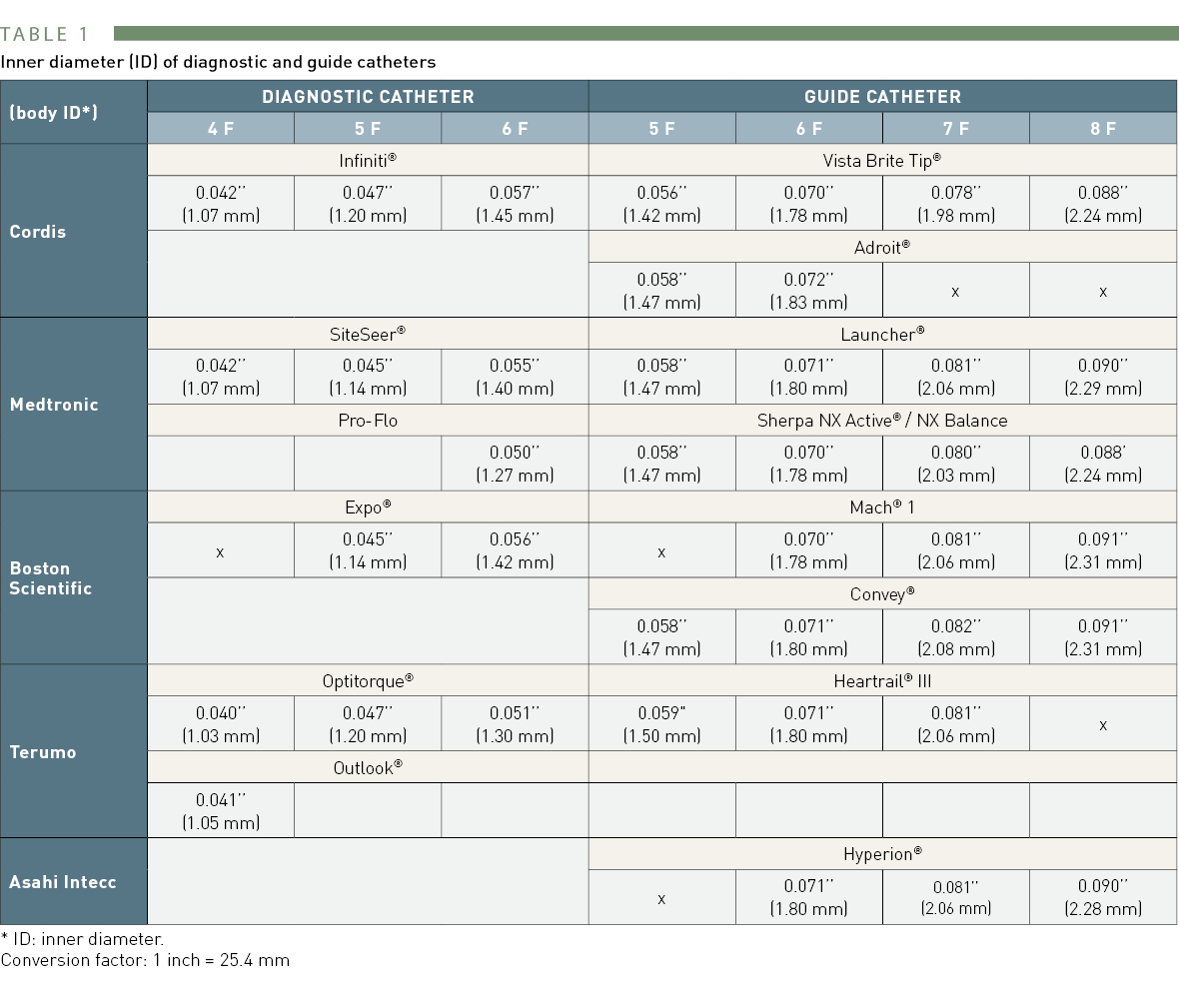
Inner diameter (ID) of diagnostic and guide catheters
* ID = inner diameter
Conversion factor: 1 inch = 25.4 mm
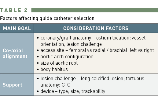
Factors affecting guide catheter selection
The 3 basic components (hub, shaft, and tip) of a guide catheter are shown in Figure GC 1. Essentially, a guide catheter comprises a catheter hub for connection, a shaft of variable size, length and stiffness, and a tip with end-hole (and sometimes with side holes) for contrast injection. Most guide catheters have inner Teflon (PTFE) lining to provide lubricious surface for passage of devices. The outer jacket is made up of polyurethane, polyamides or a variety of nylon material, into which a wire braid is integrated. The braid provides catheter strength and torque transmission. (Figure GC 2). Recent design development includes the introduction of catheters better suited for right radial approach, with optimal compromise between rigidity and flexibility, reducing the outer diameter while maintaining maximal internal lumen diameter, and having relatively non-traumatic catheter tips. Comparison of construction and design features of some 6 Fr guide catheters are shown in Table GC 3.
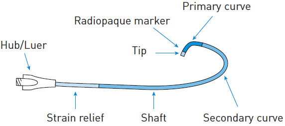
Components of a catheter
Hub – “handle” configuration.
Shaft – polyurethane or polyethylene with wire/nylon braiding to provide support and torque transmission. Catheter gradually softens from proximal to distal tip.
Tip – soft and atraumatic; of varying shape and length; radiopaque marker.
(courtesy of Medtronic)
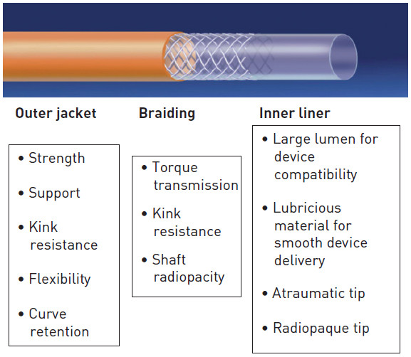
Design features of a guide catheter
[image courtesy of Medtronic]
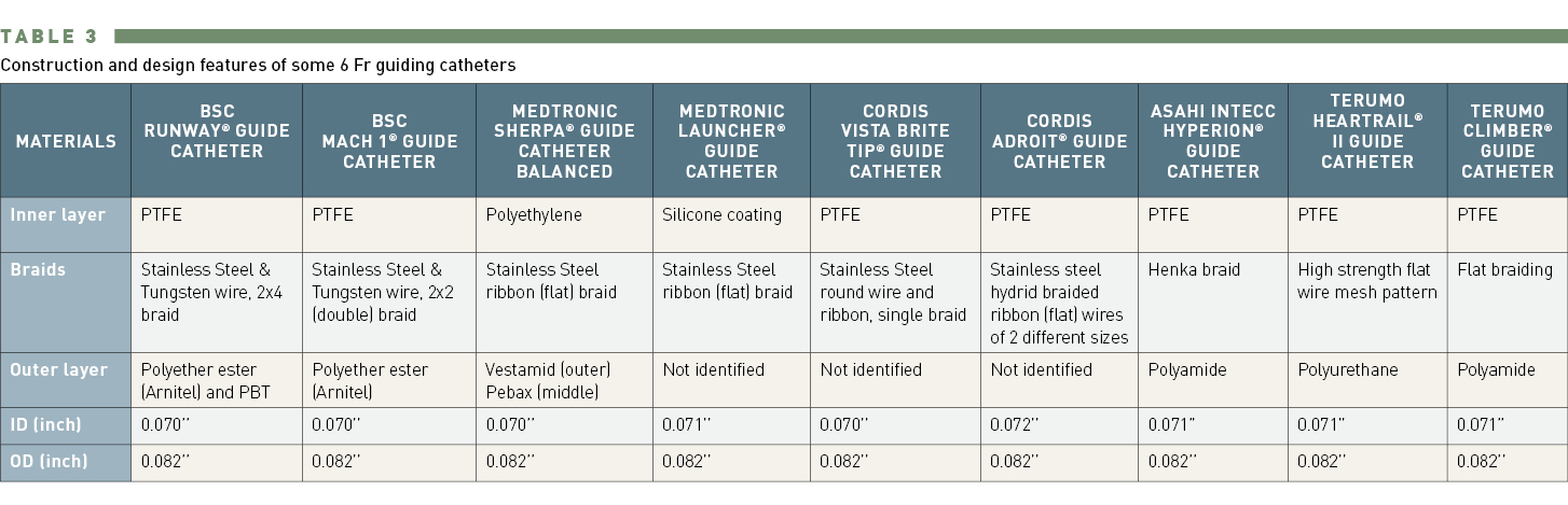
Construction and design features of some 6 Fr guide catheters
The standard length of a PCI guide catheter is 100 cm. Shorter (80–90 cm) catheters are useful for PCI of distal lesions or CTO PCI using the retrograde approach. However, they are not widely available. Use of a balloon catheter with a longer shaft length (e.g., 148 cm Ryujin® Plus; Terumo Corp., Tokyo, Japan) may circumvent the length issue in this situation. Alternatively, a guide catheter can be shortened by removing a segment of the proximal shaft, and either reconnecting the two ends with an intervening shaft cut from a sheath, or by capping with a flared, short sheath one size smaller. (Note that length reduction does not seem to significantly impact the catheter support very much. Catheter configuration / shape, size, manipulation method, construction material, have more bearing on catheter support).
Guide catheter size is defined by the outer diameter measurement, and is commonly expressed in French size (Focus box 1). Catheter size is determined by the outer diameter measurement, whereas sheath size is determined by the inner diameter measurement (Figure GC 3). The size of the guide catheter has been dramatically reduced from 9 or 10 Fr in the early days of PCI (in late 1970s and early 1980s) to 6 Fr for the majority of PCI cases nowadays. Table GC 4 lists the device/procedure compatibility with different inner dimensions of guide catheters. PCI with smaller-sized guide catheters (4 or 5 Fr) are increasingly feasible with the availability of smaller-profile balloons, stent delivery systems, guidewires (0.010’’), intracoronary imaging catheters and automated contrast media injectors. . Performing PCI using a smaller-profile system is especially important for transradial intervention (TRI) to minimise the risk of radial artery occlusion. On the other hand, larger-sized catheters provide better support with improved visibility. They facilitate the delivery of bulkier devices, and enable complex PCI involving multiple simultaneous balloon/stent deployment or IVUS-guided wiring in CTO PCI. Besides higher vascular complication rates, another drawback of a larger-sized catheter is the potential for compromising antegrade perfusion (manifests as pressure damping [Figure GC 4] when engaging the coronary ostium, due to mismatch between the catheter diameter and a small coronary ostium. Other causes of pressure damping include ostial stenosis, coronary spasm, and non-coaxial alignment of the guide catheter. To improve antegrade perfusion when a large catheter engages a small coronary ostium, catheters with side holes are helpful. They are also useful in PCI of a lesion located very proximally or at the ostium. In complex CTO PCI needing greater catheter support and concurrent use of several devices, larger-sized catheters with side holes can minimise pressure damping and the risk of vessel dissection from contrast injection. Catheters with side holes have potential drawbacks. Contrast escape from side holes may result in suboptimal opacification of the artery. Similarly, escape of bolus injection of hyperaemic agent from side holes may result in overestimation of FFR (fractional flow reserve). When guide catheter with side holes is in place, FFR should be measured using intravenous infusion of hyperaemic agent.
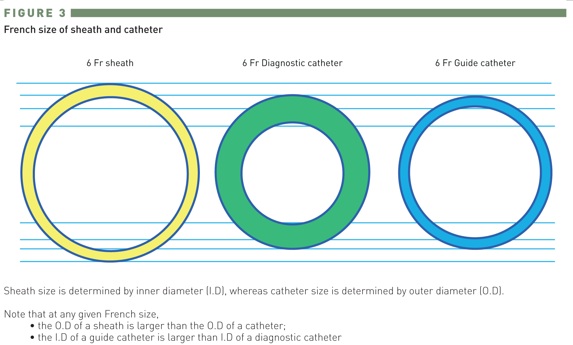
French size of sheath and catheter
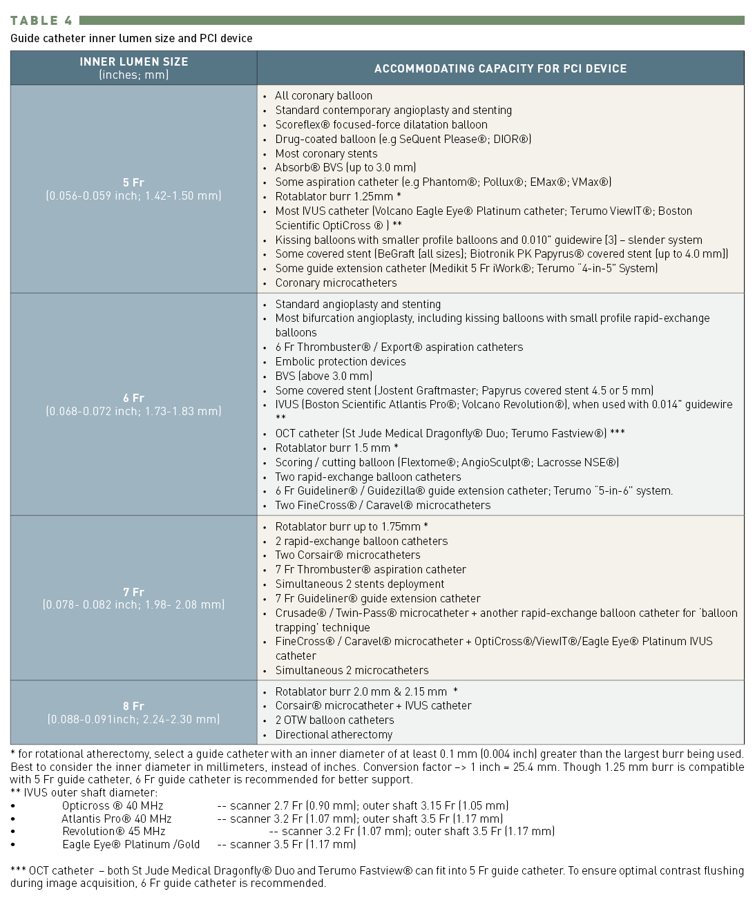
Guide catheter inner lumen size and PCI device
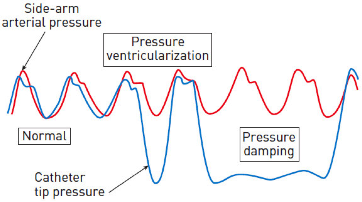
Pressure ventricularisation and pressure damping
Guide catheter shaft stiffness is determined largely by construction material (type of polymer) and thickness of the outer layer. A stiffer catheter shaft provides better support, greater pushability through tortuous anatomy, better curve retention for ostium engagement and re-engagement, with a trade-off of increased traumatic vessel injury. With PCI equipment becoming smaller and more trackable, there is a decreased need for very stiff shaft support for device passage. Depending on the compromise between rigidity and flexibility, guide catheters have different shaft stiffness (Table GC 5).
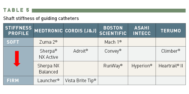
Shaft stiffness of guide catheters
The most commonly used guide catheters for the femoral approach are the Judkins, Amplatz, and Extra Back-Up support (e.g., EBU from Medtronic, XB from Cordis, Voda or Q-Curve® from Boston Scientific) catheters. Other catheters with niche use include the multipurpose catheter for the RCA bypass graft or high left main take-off, the internal mammary artery (IMA) catheter for PCI in LIMA and superiorly oriented bypass graft or RCA, and the left and right coronary bypass catheters for SVG PCI. Many catheters designed for transfemoral intervention (TFI) can also be used for transradial intervention (TRI).
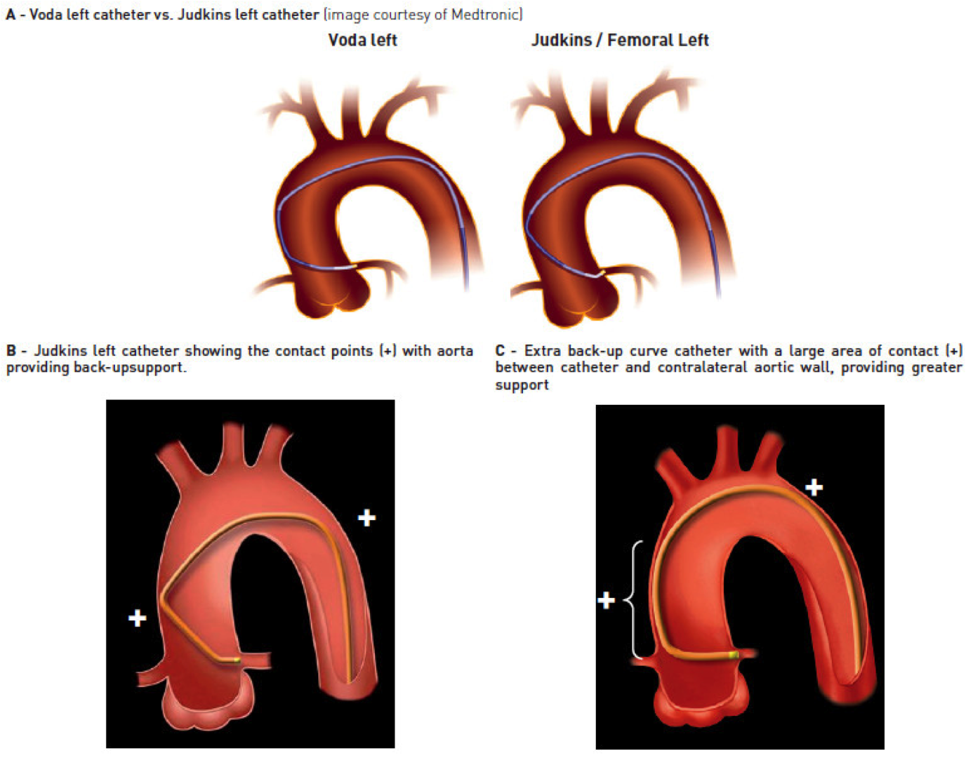
Table GC 6 lists the major factors determining guide catheter support. Catheters (e.g., Amplatz catheters) providing strong support with good back-up against the opposite wall are said to provide “passive support”. Catheters (e.g., Judkins) which can be subselectively engaged deeply into the coronary vessel or can be manipulated into a configuration conforming to the aortic root will provide additional “active support”. Becoming more popular in the last two decades are catheters (e.g., extra back-up or Voda configuration) capable of providing both the active and passive supports.
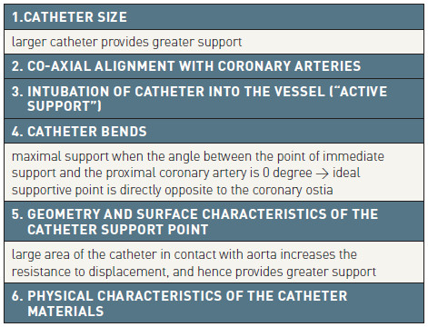
Factors determining guide catheter support
From the design standpoint, catheters can be classified into two groups: those with distal curves that are “overbent” (e.g., Judkins, Voda, Q-Curve, Extra Back-Up, XB) and those that are “underbent” (e.g., Amplatz and multipurpose) prior to insertion into the circulation. Both types of catheter have “memory”, with a tendency to maintain or return to the original configuration. The overbent catheters generally have good and predictable response, while underbent catheters are more difficult to manipulate, and may be associated with higher risks during catheter manipulation.
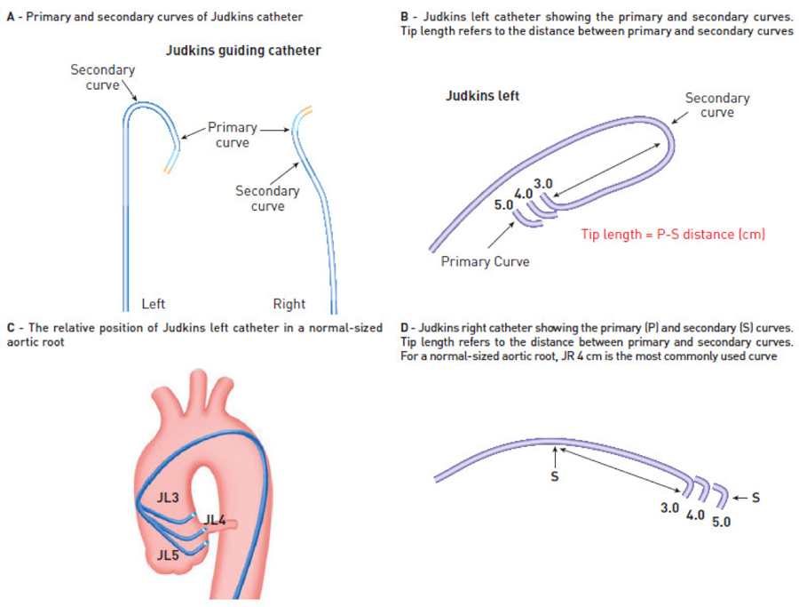
Judkins catheter
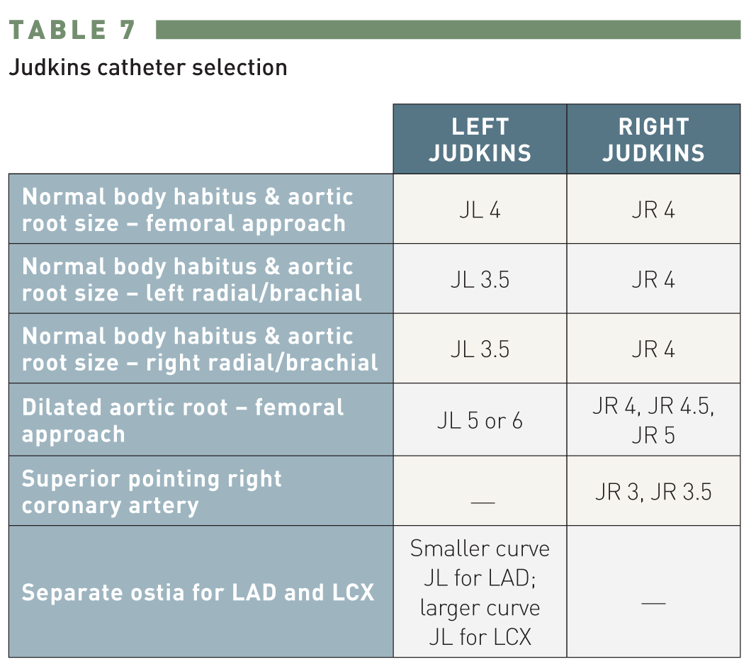
Judkins catheter selection
Judkins catheters were among the earliest catheters developed for coronary angiography. The Judkins Left Curve (JL) catheter is designed with its primary (90°), secondary (180°), and tertiary (35°) curves fitting the aortic root anatomy, allowing it to engage the LMCA ostium without much manipulation from the femoral artery. The length (in centimetres, ranging from 3.5 to 6 cm) of the segment between the primary and secondary curves determines the curve size of a Judkins catheter. In the majority of patients with normal body habitus and normal size of aortic root, Judkins left and right 4 cm curves will provide good coronary engagement. For coronary cannulation from the left radial/brachial artery approach, a Judkins left catheter with a secondary curve 0.5 mm smaller than required for femoral approach is generally better suited. The Judkins right catheter is shaped to enter into the right coronary artery with a small amount of clockwise rotation from both femoral and radial approaches. A Judkins catheter can be carefully manipulated to “deep seat” into the vessel to provide “active support”. Care must be exercised with such manipulation, however, as the 90° bend at the Judkins catheter tip does not make for perfect coaxial alignment.
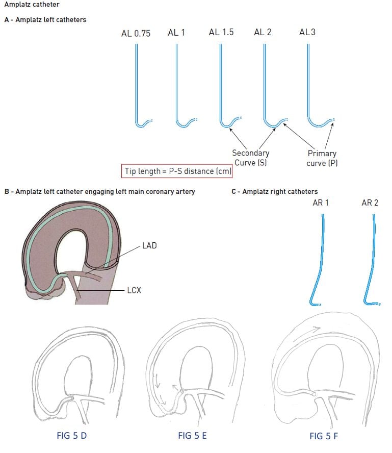
Amplatz Catheter
By resting against the back wall and aortic cusp (in non-coronary posterior aortic cusp for Amplatz left, and left aortic cusp in the case of Amplatz right), Amplatz catheters provide strong “passive support” for the advancement of wire and devices. In addition, they are often used to engage coronaries located “beyond the reach” of Judkins catheters. The Amplatz left catheter is useful for downgoing LCX or RCA, and for RCA with anterior origin in the right coronary cusp. The Amplatz right catheter is useful for engaging a horizontal or superior take-off SVG or RCA. Amplatz catheters tend to engage deeply into the coronary ostia ; hence, they are best avoided, or must be used with great caution, in the presence of aorto-ostial stenosis. Extra caution is needed when disengaging an Amplatz catheter from the coronary ostium. A simple “pullback” on the deep-seated Amplatz catheter (as is commonly done to disengage a Judkins catheter) may cause the catheter tip to “dive” deeper into the vessel, potentially resulting in vessel dissection. In this situation, the catheter is best advanced downward gently to prolapse the tip out of the ostium, before being rotated to remove the tip completely from the ostium prior to catheter withdrawal (Table GC 10).
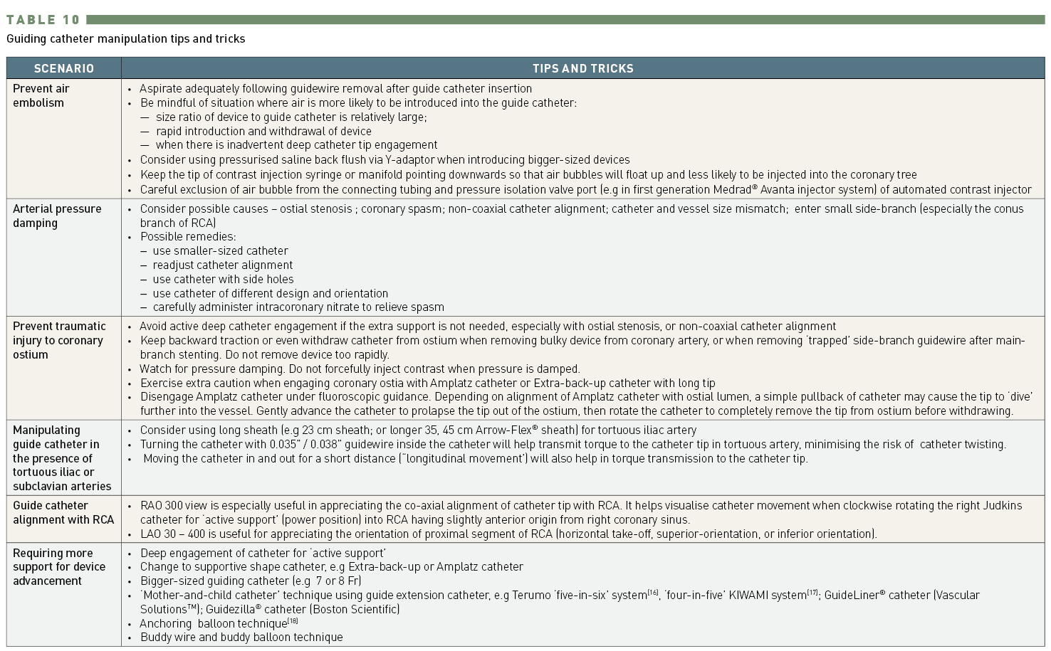
Guide catheter manipulation tips and tricks
Extra back-up curve guide catheter
This type of catheter provides a hybrid of “active” and “passive” supports. Their long tip forms a fairly straight line with the LMCA axis or the proximal part of the RCA, with the angle between the point of immediate support and the proximal artery being almost zero. This provides great support coming directly opposite to the coronary ostia. The long secondary curve provides a large area of contact between the catheter and the aortic wall, increases the resistance to displacement, and further stabilises the catheter in position. Extra back-up catheters are more commonly used for LCA intervention. Their coaxial alignment with the RCA is less predictable due to variability in RCA origin and orientation. The Voda catheter (Boston Scientific) was the first extra back-up curve catheter marketed in the early 1990s. Examples of other extra back-up catheters include the EBU (Medtronic), XB (Cordis), Q-Curve and CLS® Curve (Boston Scientific). For normal body habitus and normal-sized aortic root, the LMCA can usually be cannulated using XB 3.5 or EBU 3.5-3.75.
The multipurpose guide catheter has a slight bend (MPA 1 has 45-60° primary curve; MPB 1 has approximately 80° primary curve) some distance from the tip. It is most useful for the downward-pointing bypass graft to the RCA. Occasionally it is also used to cannulate the high LMCA take-off or inferior-pointing native RCA.
The IMA catheter (Figure GC 8) has a more angulated (80° primary curve) tip compared to the Judkins right catheter, which facilitates the engagement of IMA. From femoral approach, internal mammary artery is usually cannulated using either a Judkins right catheter or a IMA catheter, depending on the orientation of IMA in relation to the long axis of subclavian artery. The catheter is rotated anticlockwise to engage left IMA, and clockwise for right IMA. This catheter is also useful for upward-pointing RCA.
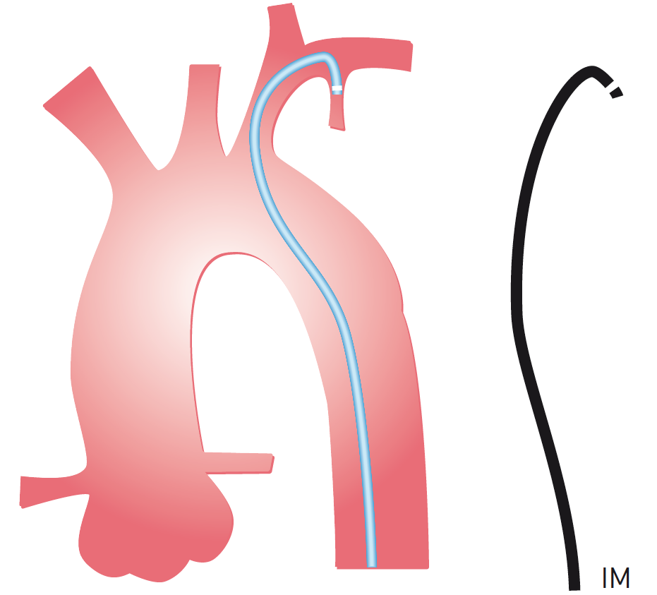
Internal mammary catheter
The left coronary bypass (LCB) catheter has the reach needed for cannulating left-sided grafts which are usually superior and to the left of the native LCA ostium.
The 3DRC (Three Dimensional Right Catheter) is used mainly to cannulate RCA with posterior or superior take-off. It has multiple curves leading to a three-dimensional configuration, and consequently does not require much manipulation to cannulate the right coronary artery as is normally done with the JR catheter.
Table GC 8 and Table GC 9 provide some guidance on selecting guide catheters.
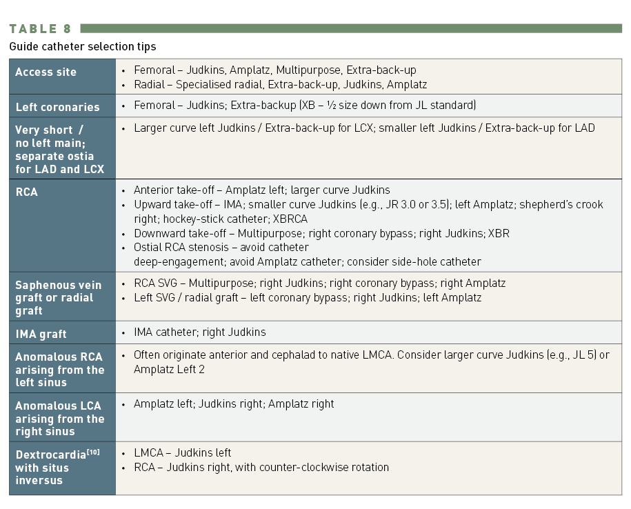
Guide catheter selection tips
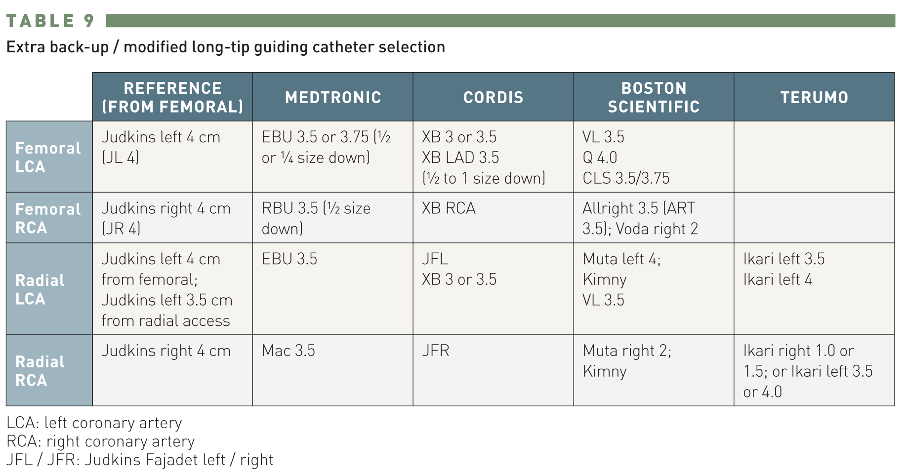
Extra back-up/modified long-tip guide catheter selection
LCA -- left coronary artery
RCA -- right coronary artery
JFL / JFR -- Judkins Fajadet left / right
Most of the development in guide catheters in the last decade has been driven by the increasing popularity of TRI. Compared to TFI, TRI reduces access site bleeding, facilitates early ambulation and lowers hospitalisation cost. Since the angle of radial approach to coronary/bypass graft ostia is different from the femoral approach, many catheters developed for TFI do not provide optimal coaxial engagement and support for TRI, especially from the right radial approach. The smaller-sized radial artery with a tendency for spasm further limits the catheter size available for TRI. Hence, both the configuration and profile of guide catheters for TRI need further optimisation.
Left TRI can be performed using standard guide catheters developed for TFI. Most of the TFI catheters can also be used for right TRI, though the catheter support is generally less. A number of modified long-tip catheters (Ikari, Kimny, Power Backup, Fajadet, etc.), mostly modelled after the triple-curved Voda catheter configuration, have been developed for right TRI , . They take into consideration the angle between the brachiocephalic trunk and the ascending aorta. These catheters provide better back-up support using the contralateral aortic wall.
Other than the factors listed in Table GC 2 for TFI, for TRI catheter selection additional anatomic factors for consideration include the position of origin of the brachiocephalic trunk from the aortic arch, and subclavian-brachiocephalic tortuosity. TRI guide catheter sizing is another important consideration.
For the left coronary artery TRI, XB, EBU and Judkins catheters are still frequently used despite providing less guide support compared to the femoral approach. When a JL4 catheter is used for TRI in vertical or normal-sized aortic root, the point of contact with the contralateral wall shifts upwards, and the resultant back-up support is 1.6 times less than the support it provides when used transfemorally . Hence, for TRI using a Judkins catheter via right RA, it is recommended either to downsize by 0.5 cm from what is used for femoral approach (i.e., JL4 for TFI à JL3.5 for TRI), or to engage deeply the JL4 catheter. Both will provide better back wall support, but still less than the JL catheter used in the normal transfemoral position. The Judkins catheter is suitable for non-complex lesions or left main stenosis when good catheter support is not critical. For some operators, extra back-up catheters (e.g., EBU, XB, Voda left, Q-Curve) or modified long-tip catheters for TRI (e.g., Ikari, Power Backup, Fajadet catheters) are the “workhorse” guide catheters for TRI. From the right radial approach, these catheters derive extra back-up support from either the sinus of Valsalva (for EBU, XB, Voda left, Q-Curve) or from the contralateral aortic wall (Ikari, Fajadet, Kimny). Sizing recommendations: (TFI) JL 4.0 à (TRI) EBU/XB 3.5, JFL/Ikari Left 4.0; (TFI) JL 5.0 à (TRI) EBU/XB 4.0/Ikari Left 4.5. These catheters enter the ascending aorta facing the right coronary sinus. They can be advanced and torqued towards the left coronary sinus over a 0.035’’ guidewire making a large J-shaped loop in the sinus of Valsalva. The guidewire is then withdrawn and the catheter tip gently manipulated to engage the left coronary artery. An inherent drawback of these catheters is the tendency for deep intubation into LAD or LCX when the LMCA is short. For complex lesions in LCX, another alternative is AL 1.5 or 2.0, which provides good passive support.
For right coronary artery TRI, again Judkins right and Amplatz right catheters are commonly used. Despite the lack of back-up support, the Judkins right catheter in sizes similar to TFI can be used for non-complex or ostial RCA lesions. Ikari right, Fajadet right, and MAC curve (Medtronic) are modified long-tip catheters (Table GC 9) designed for RCA TRI, providing back-up support using the contralateral aortic wall. Care must be exercised not to dissect the coronary sinus or RCA ostium when manipulating these catheters.
Internal mammary artery TRI is usually performed using an IMA or JR catheter via ipsilateral radial access. SVG or radial graft (with origin in the ascending aorta) cannulation is easier from the left radial approach, with standard catheters such as JR, LCB, AL, or multipurpose. Their cannulation can be difficult from the right radial access due to the proximity of origin to the innominate (brachiocephalic) artery. From the right radial approach, Judkins right and Amplatz right catheters can be used to engage SVG to left coronary arteries. Cannulation of inferior-pointing SVG to the right coronary artery can be performed using a multipurpose catheter.
A major limitation of TRI is guide catheter size, restricted by radial artery diameter and its tendency to spasm. The main concern is the risk of radial artery occlusion. A major predictor of radial artery occlusion is a larger ratio of sheath diameter to radial artery diameter. A Japanese study demonstrated that the radial artery lumen is smaller than a 7 Fr sheath in 29% of men and 60% of women, and smaller than a 6 Fr sheath in 15% of men and 28% of women. This essentially restricts the sheath and guide catheter size to < 6 Fr in most patients. Though the use of smaller (e.g., 5 Fr) sheath or catheter is associated with lower radial occlusion or stenosis rate, a smaller-sized guide catheter provides reduced catheter support with more difficult angiographic visualisation and it restricts the use of adjunctive devices or multiple balloon/stent procedures.
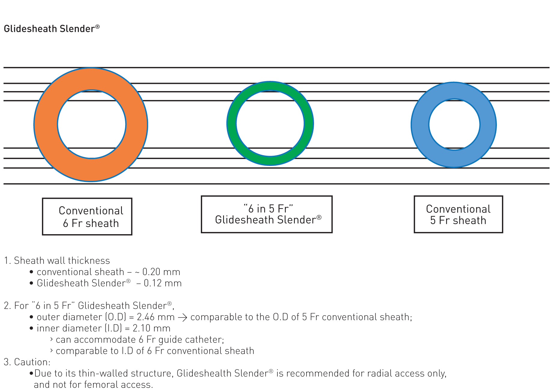
Significant progress has been in miniaturizing the whole ecosystem (the so-called “slender system”) allows TRI to be performed with smaller devices. This includes improved sheath (e.g Glidesheath Slender® with ultra-thin wall from Terumo) (Figure GC 9) and guide technology, smaller diameter guidewires (e.g 0.010” guidewires) and smaller profile devices (balloon, stent delivery system, thrombectomy catheter, IVUS, etc.) . Other than 0.010” guidewires, most of these innovations have entered into mainstream PCI.
Asahi Intecc SheathLess Eaucath guide catheter
(image courtesy of Asahi Intecc)
For guide catheters, one innovative approach is to use guide catheters that do not require an introducer sheath. This essentially reduces the equipment size within the radial lumen by ~ 2 Fr. Such a system is now popularly called the “virtual system” of comparable conventional sheath size. The size of the ‘virtual system’ refers to the ‘puncture site injury equivalent’ with the use of the conventional introducer sheath system. For simplicity, this is equivalent to the outer diameter of the conventional sheath. Attention must be paid both to the ID (inner diameter) and to the OD (outer diameter) of such catheters. For example, a 7.5 Fr Eaucath sheathless guide catheter (ID = 0.081’’, OD = 2.49 mm) (Asahi Intecc, Aichi, Japan) has an inner lumen similar to a conventional 7 Fr guide catheter but an outer diameter smaller than a 6 Fr sheath (“virtual 6 Fr system”) (Figure GC 10). A 6.5 Fr Eaucath sheathless guide catheter (ID = 0.070’’, OD = 2.16 mm) has an inner lumen similar to a conventional 6 Fr guide catheter, but an outer diameter that is less than a 5 Fr sheath (“virtual 5 Fr system”). With a smaller entry profile at the distal radial artery, a 6.5 Fr Eaucath sheathless guide catheter has a radial occlusion rate usually associated with the 5 Fr conventional system, and yet it provides the lumen size and support of a 6 Fr guide catheter. The 5 Fr Meito Masamune sheathless catheter (Medikit, Japan) has OD =1.70 mm, just slightly bigger than OD of the Medikit 3 Fr conventional introducer sheath (OD = 1.60 mm). This ‘virtual 3 Fr system’ (OD = 1.70 mm) has performance characteristic comparable to the 5 Fr conventional guide catheter with a combined OD of 2.25 mm (5 Fr guide catheter in 5 Fr sheath) . These sheathless guide catheters have hydrophilic surface coating to facilitate catheter movement in the radial artery, aiming to reduce patient discomfort and artery spasm.
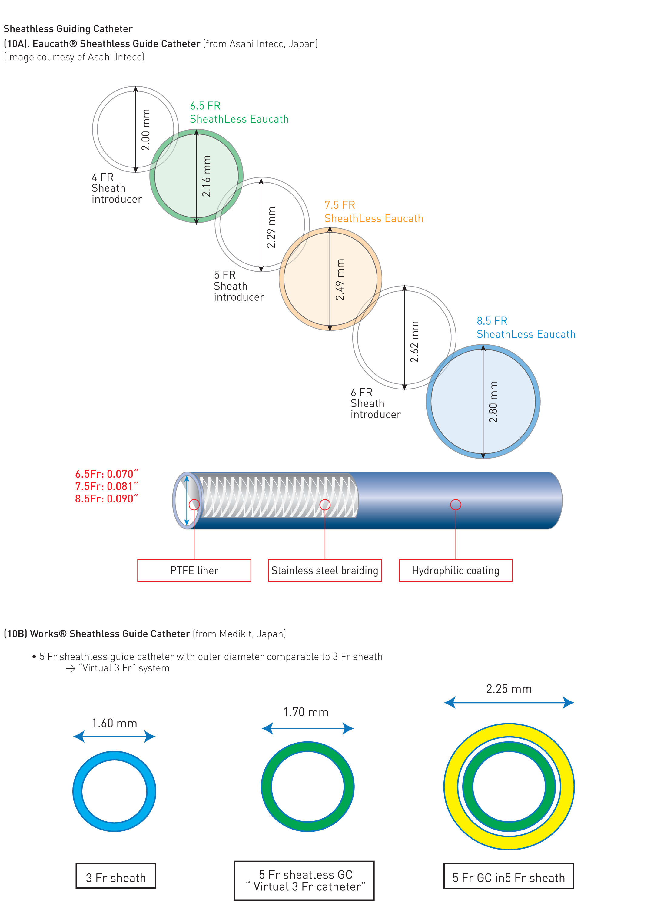
Sheathless Guiding Catheter
(10A). Eaucath® Sheathless Guide Catheter (from Asahi Intecc, Japan)
(Image courtesy of Asahi Intecc)
(10B) Meito Masamune Sheathless Guide Catheter (from Medikit, Japan)
Table GC 10 summarises some tips and tricks in guide catheter manipulation.
Enhanced guide catheter support is often required to advance the guidewire, balloon, stent, and other devices across a chronic total occlusion or a tortuous and calcified vessel. This enhanced support is often also needed to advance the balloon across the stent strut into the jailed side branch. Enhanced guider support can be obtained with (1) a larger-sized guide catheter (e.g., 8 Fr > 7 Fr > 6 Fr > 5 Fr), (2) a guide catheter with back-wall support (e.g., Amplatz, Extra back-up configuration), (3) coaxial alignment and deep engagement of the guide catheter, and (4) specific techniques involving the subselective intracoronary insertion of the wire, balloon or dedicated catheter. Two particularly useful techniques are (1) the anchoring technique, and (2) the “mother and child” catheter (double coaxial guide catheter) technique.
Either a wire (“anchoring wire”) or a balloon (“anchoring balloon”) can be used for the anchoring technique. The anchoring wire/balloon can be placed proximal or distal to the target lesion. For proximal placement, the wire/balloon is advanced into another vessel (e.g., LCX for LAD lesion) or the side branch (e.g conus branch for mid RCA lesion; diagonal branch for distal LAD lesion; OM branch for distal LCX lesion). The additional support may be provided by the anchoring wire alone or, more commonly, by inflating the anchoring balloon at low pressure in the side branch.
Distal placement of a wire often “straightens the curve” and provides additional support for balloon/stent advancement to the target lesion. This “buddy wire technique” is commonly used for a lesion in a tortuous and calcified vessel. Even greater support is afforded by inflating the balloon distally in the vessel (distal “anchoring balloon technique”) to facilitate device (usually a stent) passage.
Technical points to note when using the “anchoring technique” are summarised in Focus box 2.
Mother-and-child technique
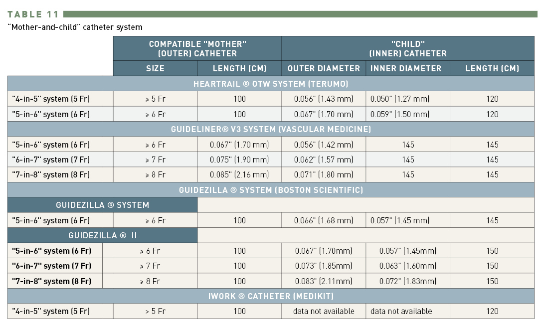
Dimensions in “mother-and-child” catheter system
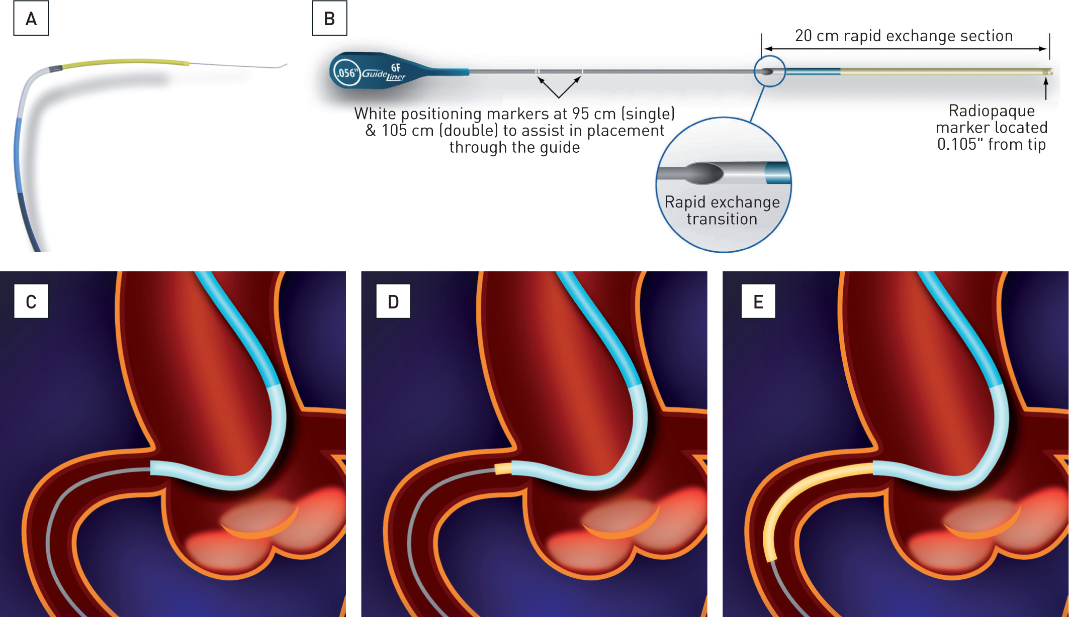
In this system, a larger outer (“mother”) guide catheter provides passive support, with added support provided by a smaller, inner (“child”) catheter (or ‘guide extension catheter’) inserted further within the target vessel. This requires the “child” catheter to be longer and smaller than the “mother” catheter. The usual length of the guide catheter is 100 cm. Several commercially available guide extension (“child”) catheters include the:
The OTW Heartrail II child catheter has a very soft 13 cm end portion. Both Guideliner and Guidezilla catheters have a stainless steel shaft and a distal 25 cm single lumen catheter (online commercial resource: www.vascularsolutions.com; www.bostonscientific.com),The GuideLiner / Guidezilla catheter can be advanced to the tip of the “mother” catheter in a manner similar to the “monorail/rapid exchange” balloon, whereas the Heartrail II and iWork® catheter are advanced in “over-the-wire” fashion.
Extreme care has to be taken when advancing the “child” catheter into the vessel to avoid injuring the proximal segment. This is best done by gently sliding the “child” catheter over the shaft of a balloon catheter, with the balloon inflated at or near to the target lesion (serving in effect as a distal “anchoring balloon”). Keeping slight tension on the balloon catheter (so-called “push and pull” technique) facilitates the gentle “child” catheter advancement.
The “mother and child” double coaxial catheter technique has rapidly emerged as one of the most useful techniques in PCI. (Focus Box 3). The system provides coaxial alignment for increased backup support for vessel with unfavourable take-off or anomalous origin. It also provides a smooth surface to help deliver the balloon/stent system in a tortuous or calcified vessel. In retrograde CTO PCI, the child catheter facilitates the entry of retrograde guidewire into the antegrade guide catheter.
The “child” catheter reduces the inner diameter of the system, potentially restricting the use of a larger-sized stent delivery system or the dual balloon technique.
When dealing with CTO or a vessel with severe tortuosity or heavy calcification, various methods of enhancing guide catheter support will be tremendously useful for a successful outcome. Understanding these techniques forms an important knowledge base for PCI operators.
As with the guide catheter, proper selection of a guidewire is critical to the success of PCI. The balloon catheter used by Grüntzig to perform the first coronary angioplasty in 1977 had a short, non-independently movable guidewire attached to its tip. The balloon and the guidewire were advanced as a single unit with limited manoeuvrability. The major breakthrough came in 1982 when Simpson et al reported the use of an independently movable, flexible-tipped guidewire within the over-the-wire balloon dilation catheter to facilitate the selection of the target vessel. The guidewire could be advanced beyond the stenosis for subsequent delivery of the balloon catheter. Guidewire technology has since progressed significantly, with a wide selection for different lesion characteristics and vessel anatomies. Understanding their properties and limitations will facilitate the selection of the appropriate guidewire for different types of lesions.
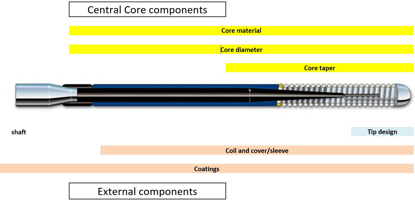
There are 3 major components of guidewire design: (1) central core, (2) distal tip, coils and cover, (3) surface coating (Figure GW 1 Figure 13). Table GW 1 explains each of the components and how they determine the overall property of the guidewire.
Components / building blocks of a guidewire
Pattern of core tapering and shaft support
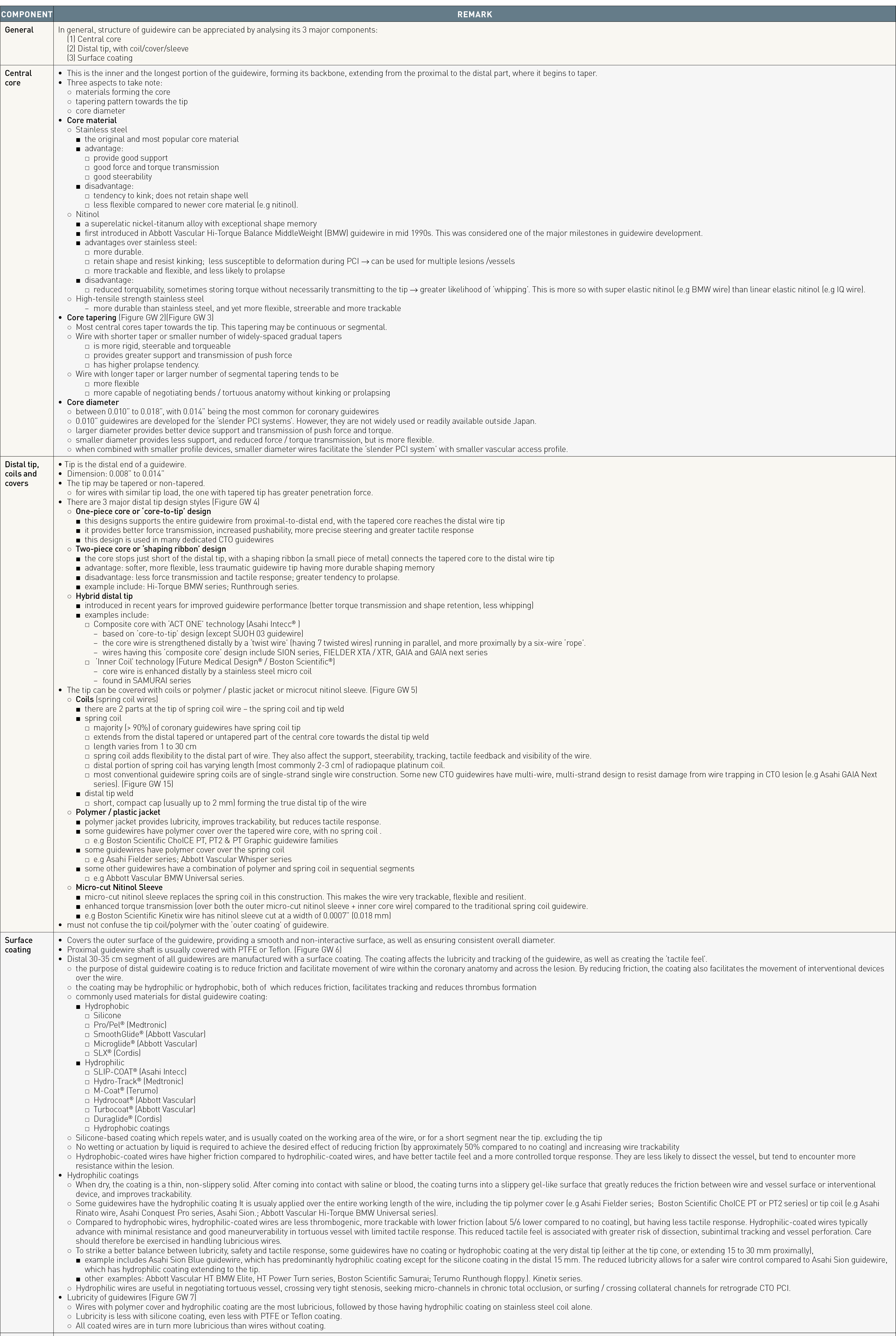
Components of a guidewire
Important physical characteristics of a guidewire and some of the common terms used to describe them are listed in Table GW 2. These characteristics are determined by the composition and design of various components of the guidewires, Figure 15. Understanding these characteristics will facilitate the appropriate selection of case and lesion-specific guidewires since no single guidewire possesses all the desirable characteristics for all lesions, Figure 14, Figure 19.
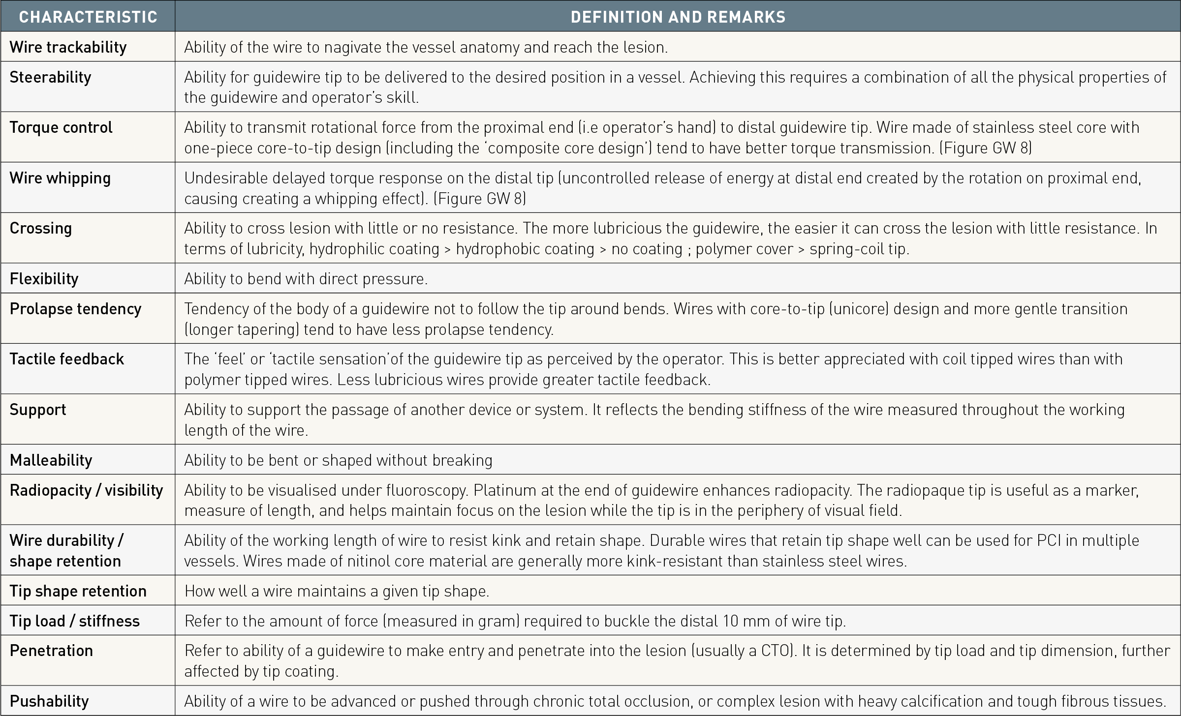
Common terms used to describe guidewire main characteris
n/a = not available
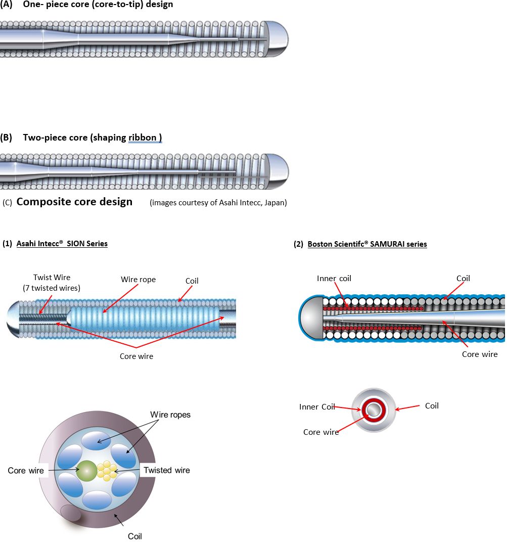
Guidewire tip design/style
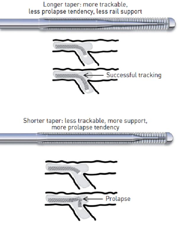
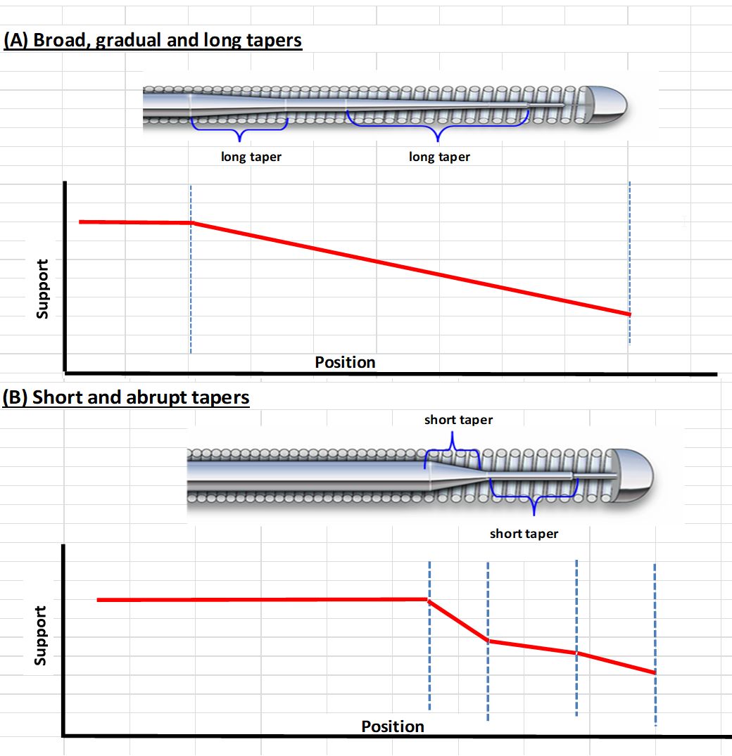
Impact of core tapering on trackability and prolapse tendency
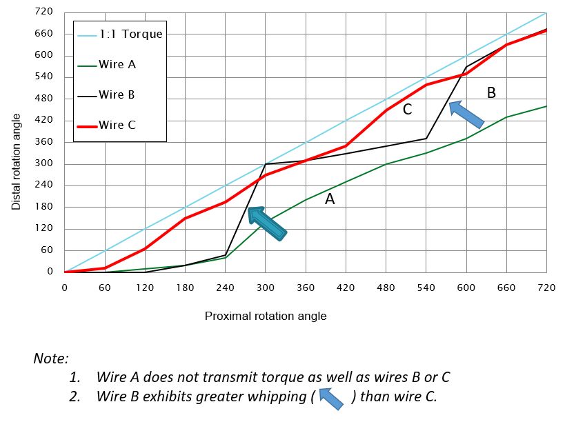
Torque transmission and wire whipping
Even though there is no uniform classification of coronary guidewires, some categorisation of guidewires can be made based on tip flexibility (floppy/soft, intermediate, stiff), tip coating (hydrophilic, hydrophobic, no coating), Figure 17, Figure 18, tip style (one-piece core-to-tip, two-piece core with shaping ribbon), tip tapering (tapered, untapered), core construction material (stainless steel, nitinol , high-tensile stainless steel), device support (light, moderate support, extra support), and target lesion type (workhorse/frontline wires, CTO wires, wires for tortuous lesions, etc.) Figure 16 (Table GW 3). There are other specific purpose guidewires, e.g., pressure wire, marker wire (with markers or length indicators), rotablator wire, wiggle wire, etc.
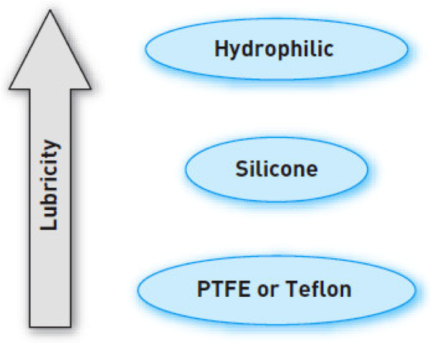
Lubricity of coating
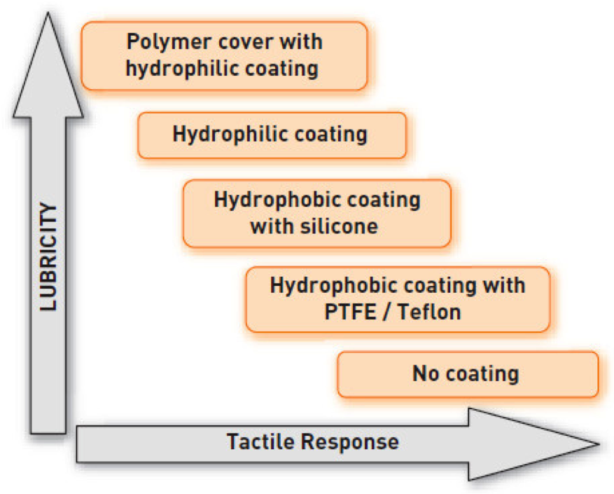
Coating, polymer, lubricity and tactile feedback
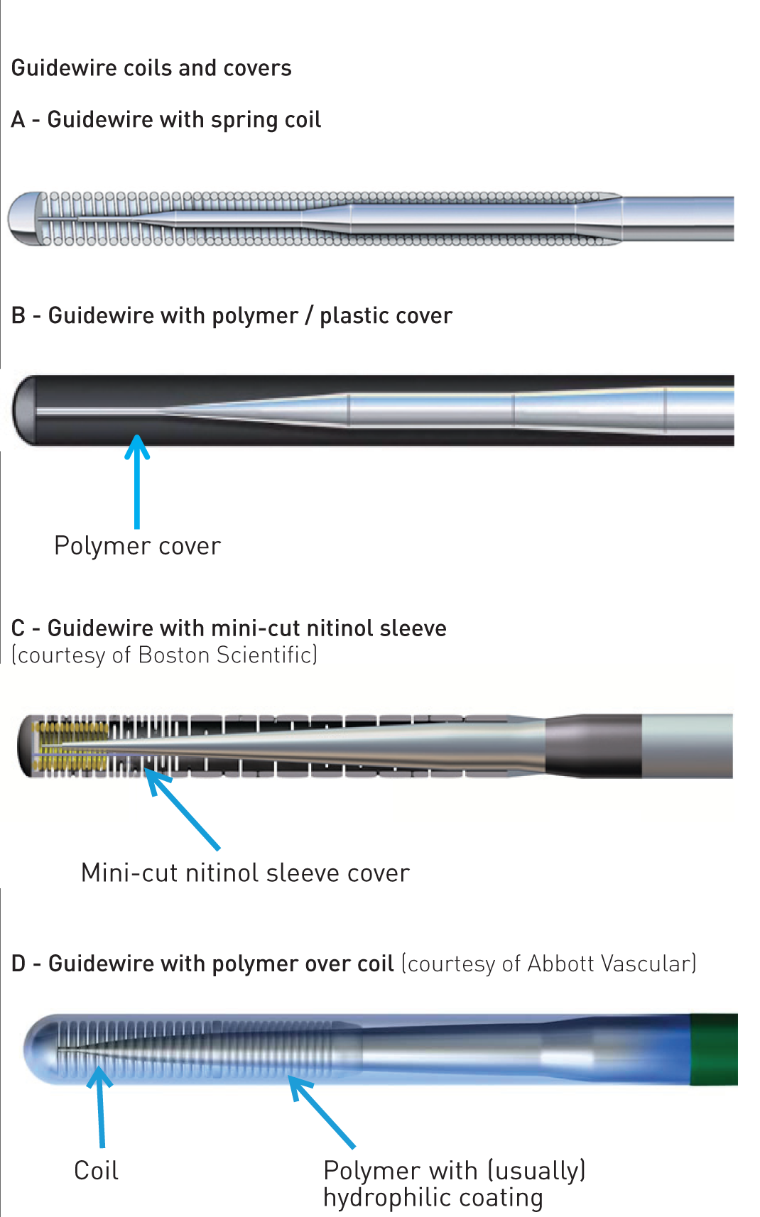
Guide coils and covers
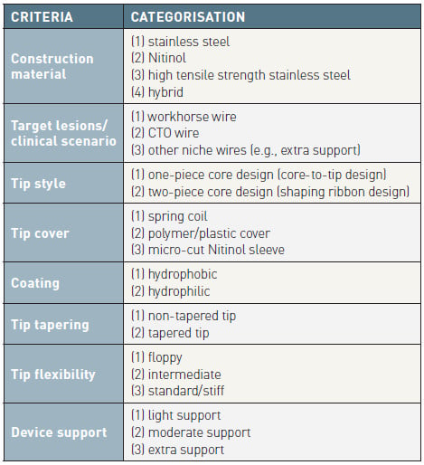
Categorisation of guidewires
“Flexibility/stiffness” of the guidewire tip is usually measured and expressed as tip load (Figure GW 9), which is the force required to buckle or bend the wire tip. The “penetration force” of a wire depends on both the tip load and the cross-sectional area of the wire tip. For wires of similar tip dimension, those with greater tip load are stiffer and have greater penetration force and pushability than ones with smaller tip load (Figure GW 10). For wires having similar tip load, those with a tapered end have greater penetration force than ones with an untapered end.
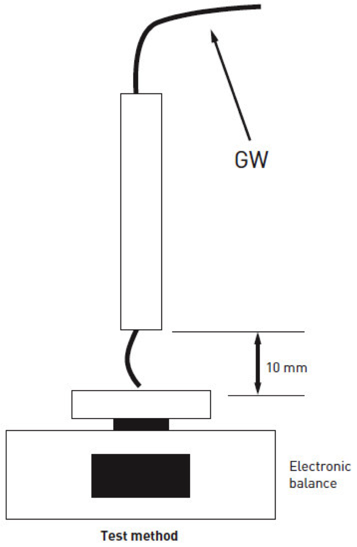
Tip load
(Courtesy of Asahi Inteccl)
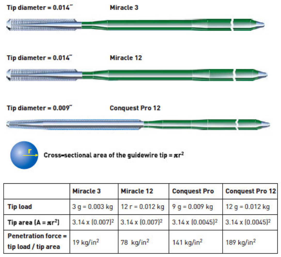
Tip load, penetration force
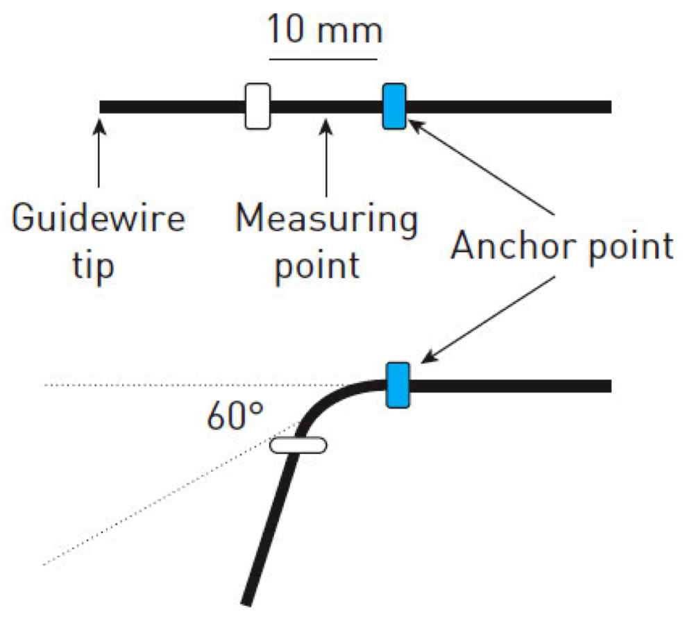
Guidewire “shaft/rail support” for device passage is measured as the force required for bending the guidewire at different distances from the guidewire tip (Figure GW 11). It is determined largely by the core diameter, core construction material and pattern of core tapering. The stiffer the shaft, the greater is the support provided for device passage through a tortuous and calcified lesion (Figure GW 12).
Guidewire support performance
Test method: measure the force required for 60° bending at different distances from the tip
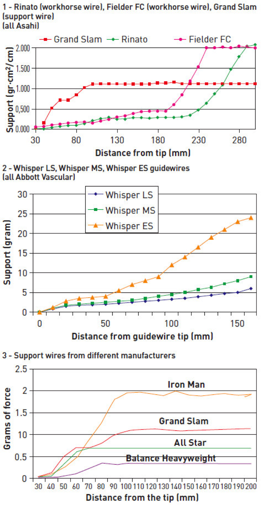
Some illustration of guidewires support performance
Test method: measure the force required for 60° bending at different distances from the tip
A more practical classification of guidewires (Table GW 4) is based on the type of lesion and the case for which the wire is used. Under this scheme, guidewires can be divided into those for (1) frontline cases (workhorse guidewires), (2) cases requiring extra support for device delivery (extra/delivery support guidewires), and (3) cases with very tight stenosis or total occlusion (access and crossing guidewires, and CTO guidewires). Figure GW 13 shows an example of this practical classification scheme for Asahi guidewires. Guidewires recommended for use in different type of lesions are illustrated in Figure GW 14.

Properties of guidewires
n/a = information not available (Special note:1) 0.010" guidewires -- TEN-NYO (Kaneka) and DECILLION (Asahi Intecc) will soon be discontinued in 2018.
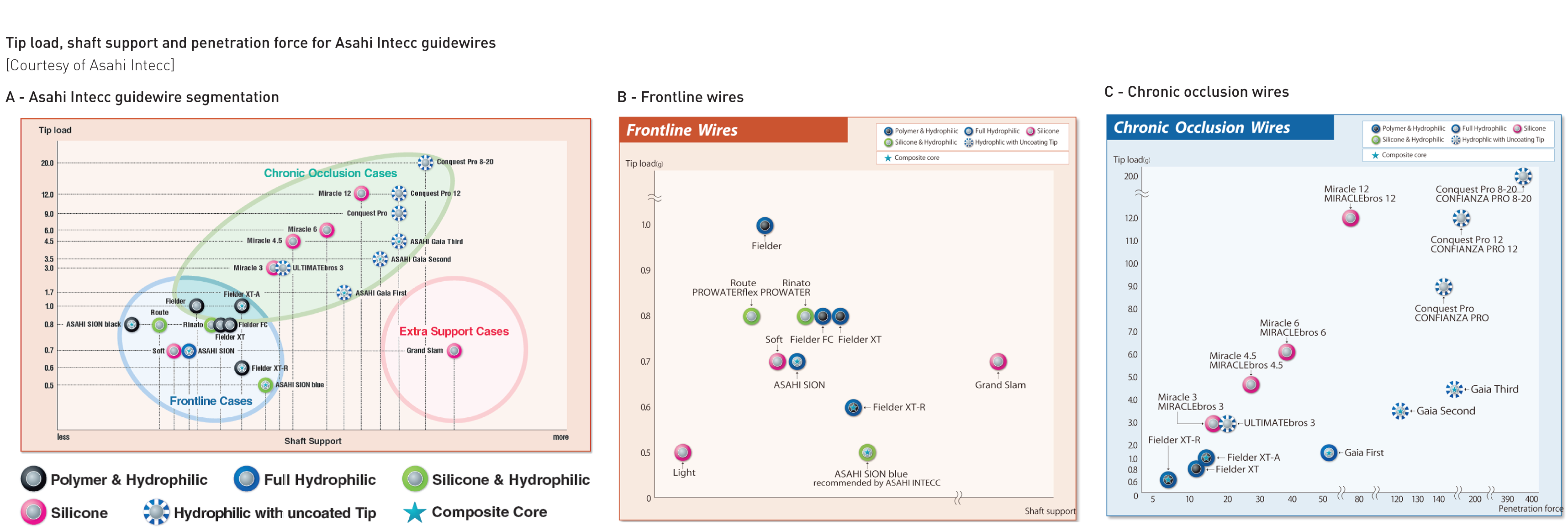
Segmentation of Asahi Intecc guidewires (Courtesy of Asahi Intecc)
(A) Asahi Intecc guidewire segmentation
(C) Chronic occlusion wires
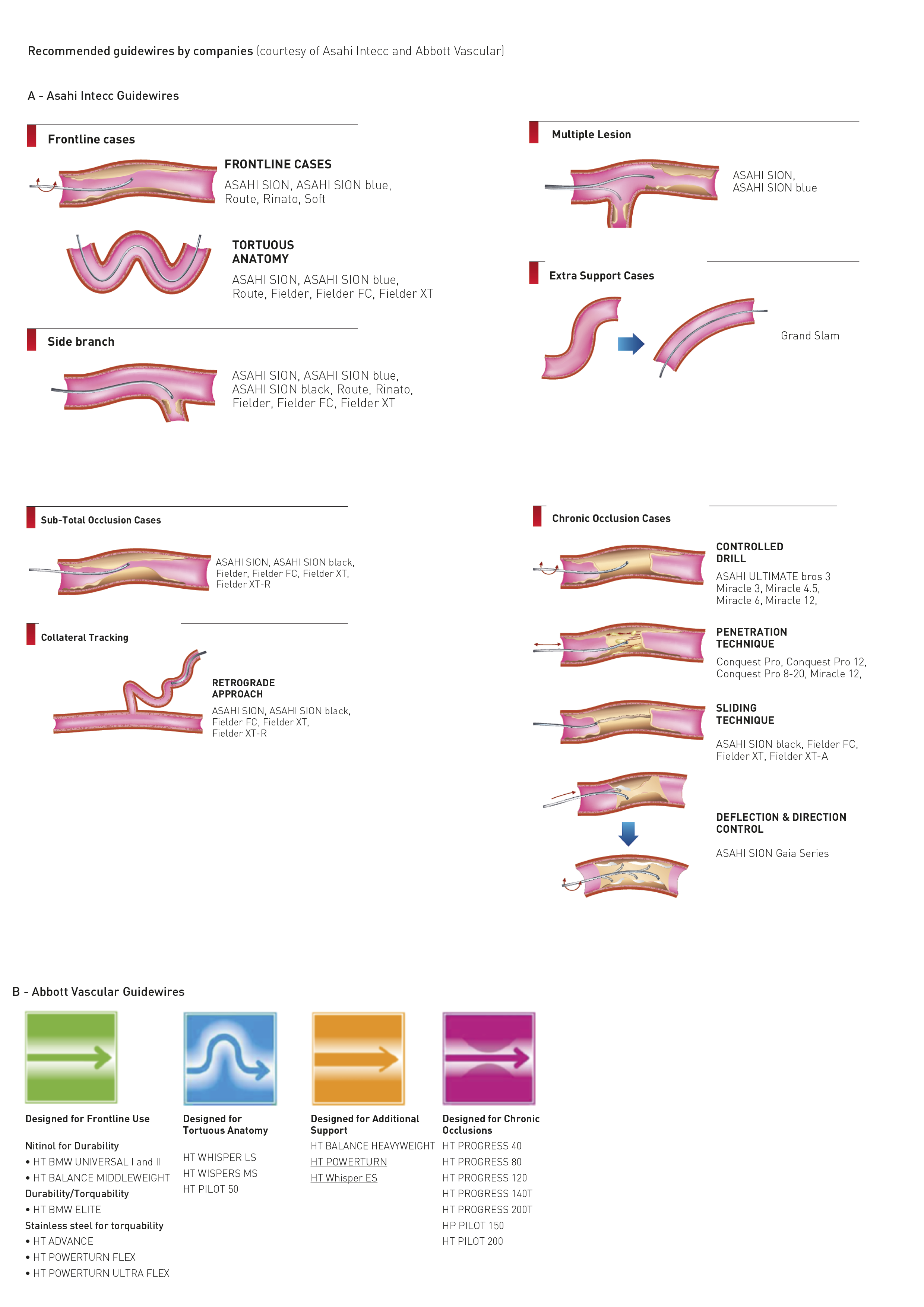
Recommended guidewires by companies
(courtesy of Asahi Intecc and Abbott Vascular)
More detailed structure of many of the currently available coronary guidewires are shown in Figure GW 15. Understanding the wire construction facilitates appreciation of guidewire properties and lesion-specific wire selection.
Diagrams courtesy of Asahi Intecc® ; Abbott Vascular®, Boston Scientific®, Medtronic®, Terumo®
Workhorse guidewires are suitable for the majority of cases/lesions. They are called “frontline/workhorse guidewires” because one or two of them form the bulk of guidewires used in any cathlab. Desirable characteristics of a workhorse guidewire include having a flexible tip that can be easily shaped, with easy manoeuvrability into the desired position. It should be able to track through a tortuous and angulated lesion, with atraumatic passage through a lesion without causing damage to the endothelium and artery. The wire should also have good torque transmission to the distal tip for more precise steering. It should provide good tactile response, besides support and lubricity for smooth device passage. The wire tip should retain the shape, or be able to reshape, for multivessel/multilesion PCI.
Workhorse guidewires strike a nice balance between tip flexibility, shaft support and steerability. They generally have a tip load that ranges from 0.5 – 1.0 g, with a wire shaft providing light or moderate support.
Extra support guidewires provide additional rail support for device delivery in challenging cases, such as a tortuous and calcified vessel, or in those having non-compliant fibrous tissue or other obstructions proximal to the target site/lesion. They are of great help when bulky devices (e.g., directional coronary atherectomy [DCA] in the past) are used. These guidewires generally have soft tips with a stiffer shaft (Table GW 4) and shorter core tapering.
Some disadvantages of extra support guidewires include causing “pseudostenoses” Figure GW 16) and guidewire bias in a tortuous vessel. At an acute bend, the stiff wire shaft can cause “cheese-cutter” effect by burying into intima/plaque. Extra support guidewires are generally less steerable, and have greater prolapse tendency.
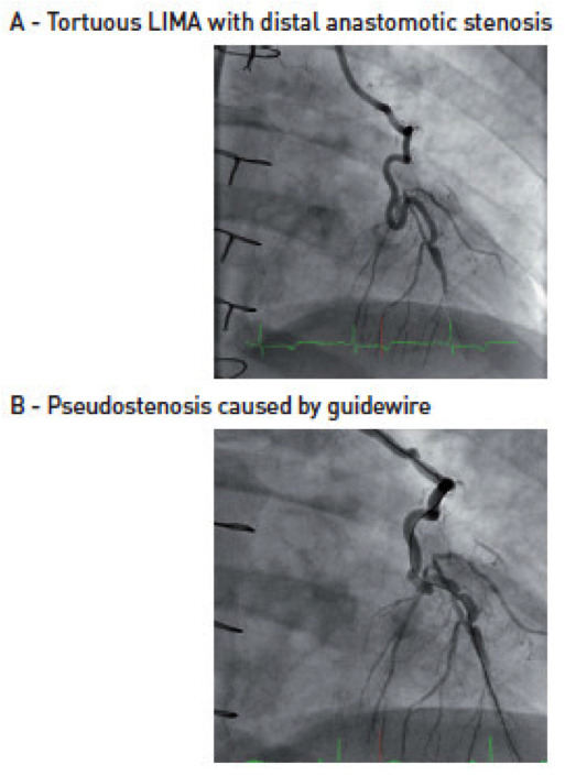
Pseudostenosis caused by wire
With the availability of support guide catheters, more flexible and more trackable balloon/stent assembly, and with the discontinuation of directional coronary atherectomy (DCA) in markets outside Japan, fewer cases now need the extra support guidewires. As a historical example, the ACS Hi-Torque Extra S’Port stainless steel guidewire was introduced in 1995 for directional coronary atherectomy. It took off when Cordis recommended this wire for its first-generation Palmaz-Schatz stent. Nowadays, it is hardly used since the majority of coronary stenting can be successfully performed with workhorse guidewires providing light or moderate rail support.
There has been much technological advancement in CTO guidewires. Other than the characteristics described for an ideal workhorse guidewire, additional properties are required for CTO guidewires to seek and traverse the microchannel, or to penetrate the hard fibrous cap and plaque, and not to be entrapped within the occlusion. To achieve these goals, most of the CTO guidewires have the following design features:
Understanding the design and properties of the chosen CTO wire is of the utmost importance for procedural success. Different CTO wires have different strengths and weaknesses, and are suitable for different CTO lesions and CTO wiring techniques (“controlled drilling” vs. “penetration” vs. “sliding” vs “deflection and directional control”). (Figure GW 14). Nonetheless, in many CTO PCI, more than one wire and one wiring technique are usually employed.
Figure GW 20 illustrates some of the principle involved in selecting guidewires for antegrade wire-based CTO PCI, as recommended by Asia-Pacific CTO (APCTO) Club.
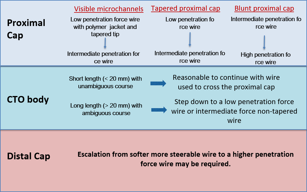
Guidewire selection for antegrade wire based strategy for CTO PCI
This technique involves controlled rotational tip motion with gentle forward probing. Operators using this technique usually start with a guidewire with moderate tip stiffness having good torqueability and tactile response. The wires (e.g., Asahi Miracle series, Medtronic Persuader 3 & 6, Abbott Hi-Torque Progress 40, 80 & 120) are usually without polymer cover at the distal wire tip, with either hydrophilic or hydrophobic coating, providing reasonably good tactile feedback. Progressively stiffer wires may be used if greater penetration force is required. Long CTO with tortuosity is best approached using the drilling or sliding technique.
This strategy generally uses stiffer guidewires, but with wire tip shape and curve similar to the drilling technique. There is more aggressive directed forward probing with minimal rotational tip motion. The wire tip movement is more precise. Heavily calcified CTO entry cap or obstructive material may require the use of a very stiff guidewire with a tapered end (e.g., Asahi Conquest Pro, Asahi Conquest Pro 12, Asahi Conquest Pro 8-20, Medtronic Persuader 9, Medtronic ProVia 15, Abbott Progress 140T and 200T) to achieve passage. This method is most suitable for shorter straight CTO with an identified near target. With stiffer wires, there is reduced tactile response and a higher risk of perforation or subintimal entry.
This strategy utilises hydrophilic guidewires, usually with polymer cover (e.g., Asahi Fielder series, Abbott Pilot series, Abbott Whisper series, BSC PT series) in softer, less calcified CTOs. Most CTOs have intraluminal microchannels , varying in size from 100-500 µm, which often run within and parallel to the thrombosed parent vessel. These microchannels provide a potential passage for the guidewire to “slide through” the CTO. Wires best suited for this purpose are those lubricious wires (hydrophilic coating, polymer cover) with a tapered end or using the newly available 0.010’’ guidewires. A tapered tip (e.g., Asahi Fielder XT, XT-A, XT-R) facilitates entry into the microchannel. Reduced surface friction (from polymer cover and hydrophilic coating) enhances passage through the body of the CTO. The guidewire tip is usually shaped with a single, long shallow bend and is advanced with simultaneous gentle tip rotation and probing. As the wire typically advances with minimal resistance and tactile feedback, there is a higher risk of subintimal entry. The sliding technique is particular useful in engaging microchannels, and in crossing subtotal occlusion. The same group of guidewires is also useful for crossing tortuous and tightly stenosed lesions.
Manipulating the wire is made easy by putting a bend at the guidewire tip. This shaping can be done using a guidewire introducer or a needle (Figure GW 17), or simply by manipulating gently between the thumb and the index finger. Avoid applying excessive force during tip shaping as this might damage the structure and integrity of the wire. For hydrophilic wire (e.g., Terumo Runthrough NS®), the recommendation is to wet the wire to activate the hydrophilic coating before shaping.
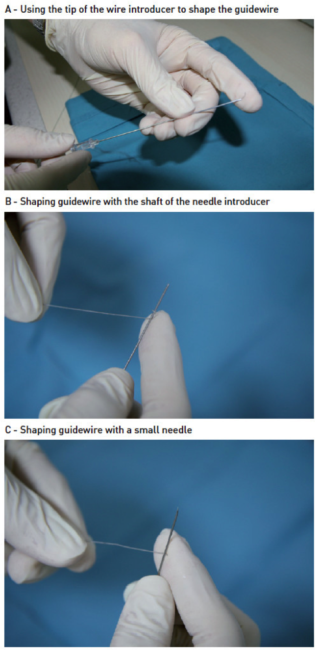
Shaping GW
The guidewire is shaped to accommodate the morphology of the target lesion and target vessel. In general, for non-occlusive lesions, the length of the distal bend should approximate to the diameter of the vessel, since a small distal bend will limit steerability and a large bend increases the risk of wire prolapse. For the majority of non-CTO lesions, a simple J-curve with a gentle distal bend is usually sufficient. A double-bend configuration (Figure GW 18) is useful for steering into steeply angled vessels.
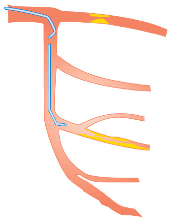
Double bend GW shape
For CTO wiring (Figure GW 19), tip shaping is important to better engage the CTO entry point and to avoid entering the subintimal space. Unlike the situation with a non-occlusive lesion (where the distal bend approximates to the vessel diameter), the desired tip curvature is usually relatively small. With the “sliding strategy”, it is recommended initially to shape the guidewire tip with a single, long shallow bend. For “drilling” and “penetrating” strategies, a commonly applied shape consists of a short tip curve (0.5-2 mm from the tip of the wire) at 45-60°, followed by a secondary proximal curve at 15-30° sited 3-5 mm from the tip adjusted to individual lesion characteristics. Use of a microcatheter may allow an adaptable change to the secondary curvature of the CTO guidewire.
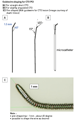
Guidewire shaping for CTO PCI
There are several ways in which over-the-wire (OTW) equipment (balloon, microcatheter, Corsair catheter, Tornus) can be moved through a standard length (175 to 190 cm) guidewire:
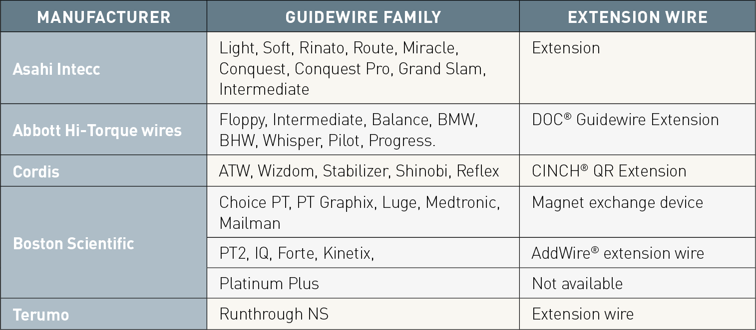
Extension wire for lengthening the standard-length guidewire
Several other special-purpose PCI guidewires are available. These include:
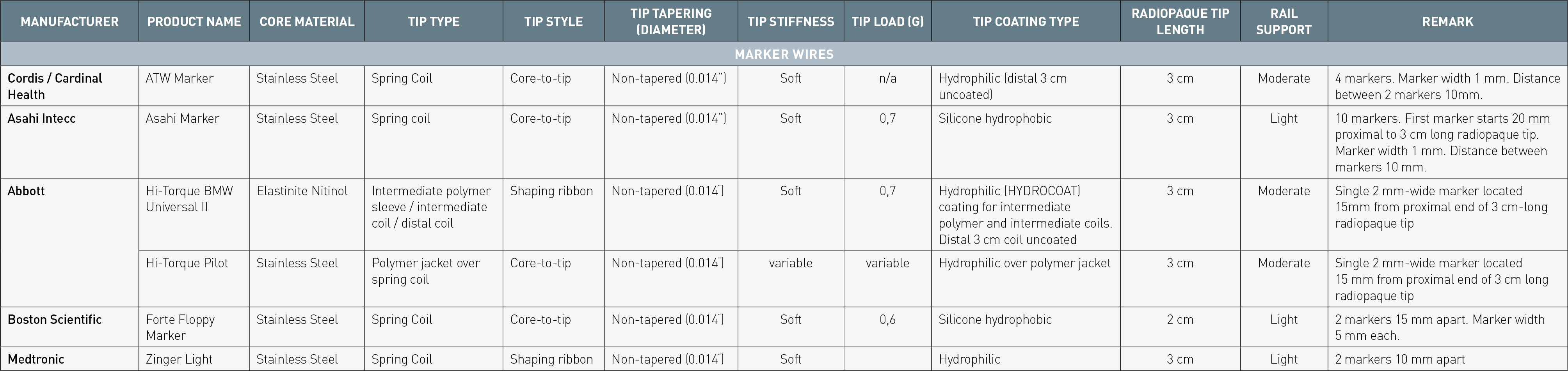
Guidewire with marker for length measuremen.
In theory, guidewire selection is influenced by vessel anatomy and lesion characteristics. In real life, guidewire selection is based more upon an operator’s experience and personal preference. Most operators will generally become familiar with a limited number of wires, and will tend to use only a small number of “workhorse guidewires” for the majority of cases. Nonetheless, operators with a good understanding of the properties of guidewires will be able to use them optimally for successful PCI when dealing with different lesion anatomies and characteristics.
Guide catheter and guidewire are basic tools for PCI. Appreciating the design features and performance characteristics will enable their optimal selection, leading to higher procedural success, lower complication rates and better overall outcome.
With the increasing popularity of TRI, a new wave of technological advances in PCI tools has taken place, driven primarily by system miniaturisation to reduce radial artery complications. Performing PCI using the virtual 3-4 Fr systems was probably unthinkable when PCI was first introduced in 1977.Better understanding of guidewires is required as operators attempt increasingly challenging lesions, especially tightly stenosed or totally occluded lesions. This attempt to conquer the “last frontier” in PCI is spurring significant improvement in guidewire technology and PCI techniques. The need exists for educating operators to better appreciate the design features and performance characteristics of new guide catheters and guidewires. After the “stentomania”, it is time to refocus on the basic tools of PCI.
Anchoring Balloon Technique - Case 1
A 75 year-old man with stable angina and abnormal stress test. Coronary angiography showed double-vessel disease, involving
RCA, LAD and first diagonal arteries. D1 was first stented. Despite adequate predilatation, intial attempt to advance the stent across the long calcified stenosis in LAD was unsuccessful. Anchoring balloon technique (with balloon inflated in the already stented first diagonal artery) was used to assist stent advancement into the distal part of mid LAD, allowing its subsequent deployment.
Moving image 1
removing OTW balloon using saline flushing method”.
Moving image 2
LCA in RAO cranial view.
Moving image 3
LCA in RAO caudal view.
MOVING IMAGE 4
LCA in LAO caudal view.
MOVING IMAGE 5
balloon dilatation of LAD calcified lesion.
Moving image 6
balloon dilatation of LAD calcified lesion.
Moving image 7
balloon dilatation of first diagonal (D1) lesion.
Moving image 8
LAD and D1 after balloon dilatation.
Moving image 9
D1 after stenting with a 2.5 mm DES.
Moving image 10
Unable to advance the stent across the entire length of calcified LAD stenosis, even though the LAD stenosis had been predilated multiple times.
Moving image 11
a 2.5 mm balloon was inflated in D1. This served as ‘anchoring balloon’ to provide enhanced support for the advancement of the 3.0 x 38mm DES into the distal part of mid LAD.
Moving image 12
deployment of 3.0 x 38 mm DES in mid LAD.
Moving image 13
deployment of a 3.5 x 12 mm DES in proximal LAD, overlapping with the distal stent in mid LAD.
Moving image 14
D1 was then rewired, and both LAD and D1 stents with post-dilated with non-compliant balloons, with final kissing balloons dilatation.
Moving image 15
Final result. RAO cranial view.
Moving image 16
Final result. RAO caudal view.
Moving image 17
Final result. LAO caudal view.
Anchoring Balloon Technique - Case 2
A 49 year-old diabetic man with acute anterior STEMI. LAD was subtotally occluded. D1 also had long diffuse narrowing. Twostent strategy with ‘mini-crush technique’ was planned. D1 was stented with a 2.5 x 36 mm DES, followed by LAD stenting with another 2.5 x 36 mm DES. D1 was rewired, but the balloon could not be initially advanced into the D1 through the stent struts in LAD / D1 orifice. A 2.5 mm ‘anchoring balloon’ was then dilated in mid LAD stented segment. The enhanced guider support allowed the passage of the balloon into the D1 stented segment. Angiographic result was satisfactory after
the final kissing balloon dilatation.
Moving image 18
initial LAD / D1 from RAO cranial view.
Moving image 19
initial LAD / D1 from LAO cranial view.
Moving image 20
after initial balloon dilatation.
Moving image 21
after initial balloon dilatation.
Moving image 22
D1 stenting with a 2.5 x 36 mm DES.
Moving image 23
D1 stenting with a 2.5 x 36 mm DES.
Moving image 24
mini-crushing of D1 stent with LAD balloon.
Moving image 25
LAD was stented with a 2.5 x 36 mm DES.
Moving image 26
LAD was stented with a 2.5 x 36 mm DES.
Moving image 27
D1 was rewired. The 2.5 mm non-compliant balloon could not be advanced into the D1.
Moving image 28
A 2.5 mm balloon was then inflated in the distal LAD stented segment. The enhanced guide catheter support provided by this LAD ‘anchoring balloon’ facilitated the passage of the second balloon into the D1 through the stent strut.
Moving image 29
LAD and D1 were then dilated with noncompliant 2.5 mm balloons, with final kissing balloons dilatation at the bifurcation.
Moving image 30
final result. RAO cranial view.
Francesco Prati, Flavio Giuseppe Biccirè
Updated on May 13, 2021
Scot Garg, Sharmaine Thirunavukarasu, Raffaele Piccolo, Patrick W. Serruys, Stephan Windecker
Updated on January 23, 2018
Kai Ninomiya, Scot Garg, Alexandre A. Abizaid, Ron Waksman, Ashok Seth, Joanna Wykrzykowska, John A. Ormiston, Patrick W. Serruys, Yoshinobu Onuma
Updated on September 30, 2022
Bruno Scheller
Updated on May 13, 2021