Intravascular ultrasound
Summary
Intravascular ultrasound (IVUS) was the first intravascular coronary imaging technique to be developed. From its inception, it was designed to overcome the limitations of angiographic luminography. This technique has made significant contributions to our current understanding of coronary artery disease through its capacity to obtain in vivo images of the vessel wall structure and its interaction with coronary devices. Knowledge of coronary vessel remodelling during atherogenesis is largely based on IVUS evidence, and many progression/regression studies of atherosclerosis are IVUS-based.
In addition, IVUS has played a key role in the field of percutaneous coronary interventions (PCI), depicting the pitfalls of stent deployment and improving stenting techniques, a major step which has dramatically decreased periprocedural complications allowing the use of the simpler antithrombotic treatments employed today and has also contributed to a decrease in long-term major cardiovascular events (MACE).
In complex subsets of PCI, IVUS is an indispensable tool, and newer IVUS catethers are being comercialized which are high definition in nature. These trends will be reviewed in this chapter, along with a review of the most important uses of IVUS in current research and clinical practice.
Introduction
Atherosclerosis is the main cause of coronary heart disease, which is today the leading cause of death worldwide and which will still be the first in the world in 2030. In the formation of atherosclerotic coronary lesions, a critical primary step is the accumulation and oxidation of low-density lipoprotein(LDL) particles.
At early stages of the formation of the atheroma, the remodelling of the vessel wall usually prevents plaque from encroaching on the lumen, thereby masking the presence of atheroma on angiography. By contrast, greyscale intravascularultrasound (IVUS) can assess fully the extension of the disease axially and longitudinally. This capability of IVUS has been used in clinical studies to follow the progression/regression of coronary plaques in patients treated with antiatherosclerotic drugs. Thus, intravascular imaging technique has played a vital role in advancing our understanding of the pathophysiologyof coronary artery disease, and in the development of novel cardiovascular drugs. In addition, it has been used extensively to assess device therapies (e.g., DES). Drug-eluting stents (DES) have revolutionised interventional cardiology. The profound ability of DES to suppress neointimal hyperplasia results in a reduced need for revascularisation and improved clinical outcomes. DES, however, are not immune to in-stent restenosis (ISR). IVUS assessment of neointimal growth has been of major value to understand the mechanisms of action of DES and also to compare different DES. Other mode of failure is stent thrombosis (ST), both events, ISR and ST can be mitigated by IVUS uitlization. More importantly, optimisation of DES deployment by using IVUS has been also associated with target lesion failure and cardiac death reduction.
The clinical and research applications of intravascular ultrasound are discussed in more detail below.
Rationale for intravascular imaging
Coronary angiography depicts arteries as a planar silhouette of the contrast-filled lumen. Importantly, angiography does not provide visualisation of the vessel wall and it is not suitable for assessment of atherosclerosis. Angiographic disease assessment is based on the comparison of the stenotic segment with the adjacent, apparently “normal” coronary, which is often an incorrect assumption due to the diffuse nature of atherosclerosis as shown by pathological and IVUS studies. (Figure 1). Angiographic interpretation is flawed by large inter and intra-observer variability and usually underestimates the severity of the disease and vessel dimensions. Although quantitative coronary angiography (QCA) has reduced the visual error, the ability of arteries to enlarge to compensate for plaque growth makes angiography an unreliable method to assess atherosclerosis burden. Unlike angiography, IVUS enables assessment of ambiguous disease in vessels with aneurysmal dilatation, ostial stenoses, disease located at branching points or in the left main, tortuous or calcified segments, eccentric disease, complex disease morphology, intra-luminal filling defects, thrombus, and dissection.
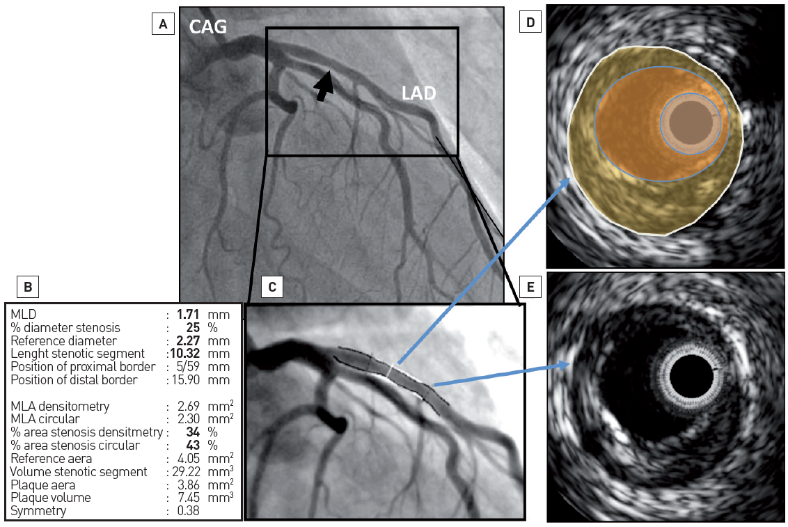
Figure 1
Luminogram versus vessel wall assessment. Coronary angiogram (CAG) only gives information about the patency of the lumen while intravascular ultrasound (IVUS) imaging can assess fully the content of the vessel wall (i.e., plaque size). In panel A, a coronary angiogram of the left coronary system is depicted. At the proximal part of the left anterior descending (LAD) artery, by quantitative coronary angiography (panels B and C), there is only mild disease (i.e., minimum lumen diameter – MLD – 1.71 mm and diameter stenosis of 25%). In panels D and E are IVUS frames. In panel D, the white circle represents the external elastic membrane, the yellow area the atherosclerotic plaque, the lumen of the coronary vessel is in orange and the IVUS catheter is in light blue. This frame is colocalised at the MLD point in the angiogram. The plaque burden is 45%. In panel E, the IVUS frame corresponds to a normal-looking segment in angiography (bottom blue arrow). In this frame, some plaque can also be seen.
BASIC PRINCIPLES
The IVUS image is the result of reflected ultrasound waves which are converted to electrical signals and sent to an external processing system for amplification, filtering and scan-conversion. After leaving the transducer, the beam remains parallel for a short distance (“near field”: better image quality) and then begins to diverge (“far field”). After encountering a transition between different materials, for example the interface between blood and the intimal arterial layer, the beam will be partially reflected and partially transmitted, depending on tissue composition and differences in mechanical impedance between materials. For example, calcium produces nearly complete backscattering of the signal and is displayed as a bright image with a characteristic acoustic shadowing. Ultimately, greyscale IVUS imaging is formed by the envelope (amplitude) of the radiofrequency signal. (Figure 2, Video Basic principles).
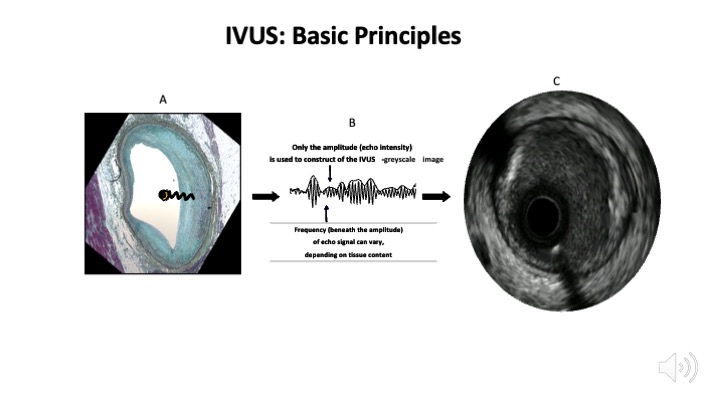
Figure 2
Intravascular ultrasound basic principles. Panel A shows how an intravascular ultrasound signal is obtained from the vessel wall within an histology image. The signal is formed by the envelope (amplitude) of the radiofrequency data, which is illustrated in panel B. The greyscale IVUS image, as can be appreciated in panel C, is the end result.
Video Basic principles
The quality of ultrasound images can be described by spatial resolution and contrast resolution. For the former, axial resolution is approximately 100 microns while lateral resolution reaches 200-250 microns in a conventional IVUS system (20-40 MHz). Contrast resolution is the distribution of the grey scale of the reflected signal and is often referred to as dynamic range. An image of low dynamic range appears as black and white with a few levels of grey whereas images at high dynamic range are often softer.
VIRTUAL HISTOLOGY (VH)
Autoregressive spectral analysis of IVUS backscattered data has been incorporated into conventional IVUS systems to facilitate image interpretation of different tissue components (i.e., necrotic core in red, dense calcium in white, fibrous in dark green, and fibro-fatty in light green). This system has been used in clinical trials to monitor progression of atherosclerosis (i.e., IBIS studies , PROSPECT , and ATHEROREMO-IVUS ) see section below. The technology is not widely available at this moment.
CATHETER DESIGNS
The IVUS equipment consists of a catheter incorporating a miniaturised transducer and a console to reconstruct and display the image. Lately, IVUS consoles have been incorporated into catheter laboratory equipment for easier operation. Current catheters range from 3.2 to 3.6 French in size and can be introduced through conventional 6-Fr guide catheters. Rotational, mechanical IVUS probes rotate a single piezoelectric transducer at 1,800 rpm and operate at frequencies between 30 and 600 MHz while electronic phased-array systems operate at a centre-frequency of approximately 20 MHz. Higher ultrasound frequencies are associated with better image resolution.
Electronic systems have up to 64 transducer elements in an annular array, which are activated sequentially to generate the cross-sectional image. In general, electronic catheter designs are slightly easier to set up and use, whereas mechanical probes offer superior image quality. Electronic IVUS catheters have the ability to display blood flow in colour to facilitate distinction between lumen and wall boundaries. Table 1.
Table 1. IVUS catheter types
| ACIST | TERUMO | PHILLIPS | PHILLIPS | PHILLIPS | INFRAREDX/NIPRO | BOSTON SCIENTIFIC | BOSTON SCIENTIFIC | |
|---|---|---|---|---|---|---|---|---|
| Catheter name | HDi | Altaveiw | Eagle Eye | Revolution | Refinity | DualPro/Makato | Opticross HD | Opticross 6 HD |
| Frequency | 40/60 MHz | 60 MHz | 20 MHz | 45 MHz | 45 MHz | 35-65 MHz | 60 MHz | 60 MHz |
| Resolution: axial | 40 μm | 200 μm | 100 μm | <50 μm | <50 μm | 20 μm | 22 μm | 22 μm |
| Resolution: lateral | 90 μm | 200 μm | 250 μm | 100-200 μm | 100-200 μm | <200 μm | 50-140 μm | 50-140 μm |
| Compatible wire size | 0.36 mm | 0.36 mm | 0.36 mm | 0.36 mm | 0.36 mm | 0.36 mm | 0.36 mm | 0.36 mm |
| Tip entry profile | 1.7 F | 1.7 F | 1.5 F | 1.7 F | 1.9 F | 2.4 F | 2 F | 1.3 F |
| Proximal Shaft profile | 3.6 F | 3.2 F | 3.5 F | 3.5 F | 3.0 F | 3.6 F | 3.0 F | 3.6 F |
| Usable length | 142 cm | 137 cm | 150 cm | 135 cm | 135 cm | 160 cm | 135 cm | 135 cm |
| Length from tip to sensor | 20 mm | 24 mm | 2.5 mm | 29 mm | 20.5 mm | 21 mm | 20 mm | 20 mm |
| Frame rate | 60 fps | 100/160 fps | 30 fps | 30 fps | 30 fps | 30 fps | 30 fps | 30 fps |
| Pullback speed | 10 mm/sec | 10/20/30/40 mm/sec | Manual, 0.5/1.0 mm/sec | 0.5/1.0 mm/sec | 0.5/1.0 mm/sec | 0.5/1.0/2.0 mm/sec | 0.5/1.0 mm/sec | 0.5/1.0 mm/sec |
| Pullback length | 12 cm | 15 cm | 15 cm | 15 cm | 15 cm | None provided | 10 cm | 10 cm |
EXAMINATION TECHNIQUE
The IVUS procedure is performed under full anticoagulation with an activated clotting time of >250 sec. Following intracoronary infusion of intracoronary nitroglycerine (100- 200 micrograms) to minimise vasospasm, the rapid exchange IVUS catheters are introduced in the coronary over a standard 0.014” guidewire. Mechanical IVUS systems require infusion of heparinised saline to clear air bubbles inside the sheath covering the transducer before inserting the catheter into the guide catheter. The IVUS catheter should be advanced under fluoroscopic guidance approximately 10 mm distal to an anatomical landmark (e.g., side branch) and retracted slowly to straighten the catheter shaft which may have built some slack during insertion in order minimise non-uniform rotation distortion (NURD) artefacts. Motorised pullback devices should be used to withdraw the catheter at a constant speed (most frequently at 0.5 mm/sec) to allow proper examination of the entire coronary as well as calculation of distances. Unless coronary ischaemia ensues, the catheter should be withdrawn up to the aortic coronary junction, as the guide catheter should be retracted slightly to allow imaging of the coronary ostium.
IVUS co-registration with angiography systems (e.g. SyncVision, Phillips, Rancho Cordova, CA, USA) enable a joint display of images acquired by X-ray and IVUS. By clicking on any point in the coronary angiography image, the corresponding IVUS cross-section is displayed. This allows a comprehensive analysis of the target lesion and also of the lesion length and vessel diameter. This information helps to outline the best strategy for lesion preparation and stent size selection, thereby avoiding geographical miss. Unfortunately, only IVUS 20 MHz catheter is supported.
SAFETY
IVUS imaging has been performed safely in a large number of subjects enrolled in research studies with no apparent increase in the incidence of adverse effects. In one study, the rates of complication were as follows: 2.9% of patients experienced transient spasm and 0.4% of patients had acute vessel occlusions, dissections, and/ or embolism. The complication rate was higher in patients with unstable angina or acute myocardial infarction and in patients undergoing intervention compared with diagnostic IVUS.
The long-term safety of IVUS in transplant recipients has been reported. Subsequent angiographic stenoses were observed in 19.5% (107/548) of IVUS imaged arteries vs. 16.2% (21/130) of non-imaged arteries (p=0.4). Another study reported on 18 to 24-month quantitative coronary angiographic analysis comparing IVUS-imaged and non- IVUS-imaged arteries in 525 patients. New stenotic lesions occurred in 3.6% and 3.9% of IVUS-imaged and non-IVUS imaged arteries respectively (p=0.84). When all coronary lesions were considered, the incidence of lesion progression was not significantly different between IVUS-imaged (11.6%) and non-IVUS-imaged (9.8%) arteries.
One can conclude that the use of IVUS imaging is safe as confirmed by the low rate of complications and the absence of lesion progression in coronary arteries imaged with this technique. Operators must perform IVUS pullbacks carefully especially in tortuous vessels, while performing pullbacks in left circumflex (LCX) coronary artery, small vessel or distal segments. In fact, while attempting distal segments, it is also important to consider that in the mechanical catheters the transducer is slightly proximal to the actual tip of the IVUS probe, so the tip of the catheter may injure the distal end of the vessel.
LIMITATIONS AND IMAGE ARTEFACTS
Greyscale IVUS provides a limited insight into atheroma composition. Soft (echolucent) plaques have been related either to high lipid content or to the presence of smooth muscle cells. While fibrous plaques usually have an intermediate echogenicity, sometimes very dense fibrous plaques can also appear as calcified lesions. Traditionally, acoustic shadowing has been considered as a sign of calcification, but necrotic tissue can also cause shadowing. In addition, the inter-observer variability in the plaque type assessment by greyscale IVUS reported in the literature varies considerably, with percentages of concordance between observers ranging from 88% to only 47%.,
Most artefacts of IVUS imaging are specific to the construction of each system. NURD is specific to mechanical catheters and arises from friction of the transducer in the coronary or guiding catheter or from a poor connection of the IVUS catheter in the motor drive unit, which typically causes the appearance of an ‘’onion skin’’ image in a sector of the image. Tortuosity, severely stenotic segments, small guide lumen size, guide catheters with sharp secondary curves or slack in the catheter shaft or tightened haemostatic valve are common causes of NURD. The ring-down artefact, however, is specific to electronic systems due to transducer oscillations which obscure the near-field image. Side lobes artefacts are intense reflections that come from strong reflectors such as calcium and stent struts. These usually follow the circumferential sweep of the beam. The presence of the side lobes may mask the actual lumen edge and may also be taken as tissue prolapse or dissection flaps. Another artefact, which also comes from strong reflectors, is reverberation. Reverberations are concentric repetitions of the same image at equidistant locations.
An eccentric or non-perpendicular position of the IVUS catheter produces geometric distortions and an artificially elliptical appearance of the cross-sectional image leading to overestimation of lumen area.,
The speed of catheter pullback is also prone to errors which may lead to incorrect assessment of the length of the segment of interest. Unlike non-sheath based catheters (electronic system), sheath-based, mechanical catheter systems allow more uniform pullbacks during image acquisition and more precise length measurements. All these factors should be considered when assessing IVUS images to avoid misinterpretation, which could lead to erroneous clinical decisions.
HYBRID INTRAVASCULAR IMAGING MODALITIES
Hybrid (i.e. combined) systems that integrate IVUS and OCT into a single catheter have emerged as a promising tool for diagnosis and guidance during PCI, as they merge the inherent strengths of both technologies. For example, IVUS can accurately quantify plaque burden (PB) and detect calcific tissue, while compared to IVUS, OCT has superior efficacy identifying lipid tissue, measuring fibrous cap thickness and portraying plaque micro-characteristics that are unseen by IVUS and are associated with increased vulnerability such as macrophages accumulation, neovessels and cholesterol crystals. (Figure 3).
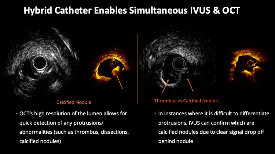
Figure 3
Hybrid Catheter Enables Simultaneous intravascular ultrasound (IVUS) & optical coherence tomography (OCT). On the left half of the figure, corresponding IVUS and OCT frames help to evaluate luminal protrusions. On the right side of the figure, the example shows the value of concomitant evaluation for the desambiguation of thrombus versus calcified nodule.
NOVASIGHT HYBRIDTM is an FDA and PMDA approved system with the following catheters pecifications : 2.8Fr imaging window, 40MHz IVUS, 12mm distal tip to imaging core, 6F guide catheter compatibility and 149cm workable length. It has different imaging modes :
- Live IVUS scout imaging mode ;
- Hybrid IVUS OCT pullback speeds: 25mm/s, 10mm/s ;
- IVUS-only pullback speeds: 5mm/s, 1mm/s, 0.5mm/s and all imaging modes are customizable in length up to 100mm (Video Hybrid IVUS and OCT).
Characterisation of atherosclerosis
NORMAL CORONARY ARTERY STRUCTURE
One first needs to understand the structure of a normal coronary artery in order to differentiate it from its pathological conditions. The arterial wall of coronary arteries is composed of three layers. The innermost tunica intima is in direct contact with the blood and is constituted by an endothelial cell monolayer resting upon a basement membrane. Aging of human arteries is associated with the presence of smooth muscle cells in the tunica intima. These cells produce extracellular matrix molecules leading to intimal layer thickening. This process is not necessarily associated with pathological lipid accumulation and atherosclerosis formation. The second layer, tunica media, is separated from the tunica intima by the internal elastic membrane (IEM) and is formed by concentric layers of smooth muscle cells. The adventitia is the outermost arterial layer, which is separated from the media by the external elastic membrane (EEM), and contains fibroblasts and mast cells, collagen fibrils, vasa vasorum and nerve endings. (Figure 4, Moving image figure 4).
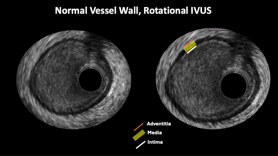
Figure 4
A rotational intravascular ultrasound showing the tree layer normal appeareance of the vessel wall.
Moving image figure 4
The normal coronary architecture can be assessed using IVUS. The circulating blood may assist IVUS image interpretation and differentiate lumen from vessel wall, as these produce characteristic speckles in the image. However, blood speckles are dependent on flow velocity and may have increased intensity during slow blood flow, and under such conditions may have a similar appearance to the vessel wall. This is particularly evident when high frequency transducers are used. The reported normal value for intimal thickness in young subjects is typically 0.15±0.07 mm. Thus, the thin tunica intima reflects ultrasound poorly and is not visualised as a separate layer. The media is typically less echogenic than the intima, but may appear thick because of signal attenuation and weak reflectivity of the internal elastic membrane. The adventitia has the strongest echo signal, which is used as a reference to determine plaque components. Importantly, the IVUS beam penetrates beyond the adventitial layer allowing visualisation of perivascular structures, including the cardiac veins and the pericardium. Based on histological and ultrasound data, a coronary vessel wall with an intimal thickness ≥0.5 mm is considered to be diseased.
ATHEROMA
A detailed description of atherosclerosis development and composition is beyond the scope of this chapter. In brief, an atheroma is formed by an intricate sequence of events, not necessarily in a linear chronological order, which involves extracellular lipid accumulation, endothelial dysfunction, leucocyte recruitment, intracellular lipid accumulation (foam cells), smooth muscle cell migration and proliferation, expansion of extracellular matrix, neoangiogenesis, tissue necrosis and mineralisation at later stages. The ultimate characteristic of an atherosclerotic plaque at any given time depends on the relative contribution of each of these features. Thus, the pathological intimal thickening (PIT) is rich in proteoglycans and lipid pools, but no trace of necrotic core is seen. The earliest lesion with a necrotic core is the fibroatheroma (FA), and this is the precursor lesion that may give rise to symptomatic heart disease. Thin-capped fibroatheroma is a lesion characterised by a large necrotic core containing numerous cholesterol clefts. The overlying fibrous cap is thin and rich in inflammatory cells, macrophages and T lymphocytes with few smooth muscle cells. A cut-off value for cap thickness of <65 microns to define a vulnerable coronary plaque has been based on pathology studies, but in vivo confirmation of such a threshold is lacking.
Based on tissue echogenicity (i.e., their appearance) and not necessarily histological composition, atheromas have been classified into four categories by greyscale IVUS (Figure 5):
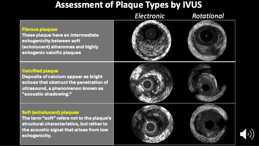
Figure 5
Assessment of plaque types by intravascular ultrasound. The IVUS consensus paper definitions are shown on this slide.
- soft plaque (lesion echogenicity less than the surrounding adventitia - hypoechoic);
- fibrous plaque [intermediate echogenicity between soft (echolucent or isoechoic) atheromas and highly echogenic calcified plaques];
- calcified plaque (echogenicity higher than the adventitia with acoustic shadowing); and
- mixed plaques (no single acoustical subtype represents > 80% of the plaque).
Another greyscale IVUS classification has been widely used (Video Plaque types):
Video Plaque types
- Echo-attenuated plaques have no ultrasound signal behind plaque. This plaque can be either hypoechoic or isoechoic but contained no bright calcium
- Echolucent plaque present an intraplaque hypoechoic zone surrounded by tissue of greater echodensity.
Virtual histology has been proposed to give better insight into tissue characterisation , and has been used in randomised clinical trials and natural history studies to evaluate the temporal changes in tissue and plaque types. As mentioned above, IVUS-NIRS have reported clinical studies of a similar nature.
DETECTION OF CALCIFICATION
The presence, depth and circumferential distribution of calcification are important factors not only for selecting the type of interventional device and for estimating the risk of vessel dissection and perforation during PCI, but also in designing and conducting studies on progression/regression of coronary atheroma. Plaques with moderate to severe calcification showed neither change nor progression of atheroma size. Furthermore, in the presence of severe calcification, severe shadowing may prevent an accurate assessment of the total plaque burden. Thus, careful selection of coronary segments to evaluate the effect of drugs on coronary atherosclerosis should be considered.
On IVUS, calcium appears as bright echoes that obstruct the penetration of ultrasound (acoustic shadowing). Therefore, IVUS detects only the leading edge of calcium and cannot determine its thickness. Calcification on IVUS is usually described based on its circumferential angle (arc), its longitudinal length and its depth. Calcification can be located deeper in the arterial wall or in the surface of the plaque, in close contact with the lumen wall interface. Figure 6. As mentioned above, calcium can produce reverberations or repeated reflections at reproducible distances. IVUS has shown significantly higher sensitivity than fluoroscopy in the detection of coronary calcification. Virtual histology, as compared to histology, has a predictive accuracy of 96.7% for detection of dense calcium.
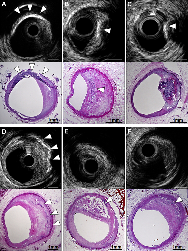
Figure 6
Coronary calcification. In the upper examples, IVUS-detected segments with superficial calcification (white arrowheads) were seen to be calcified fibrous plaque (A), FA with spotty calcium (B), and calcified nodule (C) on pathological images. (D) IVUS detected deep calcium in the setting of calcified fibrous without overlying NC (white arrowheads); (E) conversely, IVUS failed to detect spotty calcium (white arrowhead) that was present pathologically, because it was hidden behind a large NC within a late FA that caused attenuation. (F) Finally, microcalcification (white arrowhead) within the NC of an early FA was not detected by IVUS but produced echo attenuation. Bar = 1 mm. FA, fibroatheroma; NC, necrotic core.
ARTERIAL REMODELING
Arterial remodelling refers to a continuous process involving changes in vessel size measured by the EEM cross-sectional area (also called vessel cross-sectional area - CSA). Positive remodelling occurs when there is an outward increase in EEM. Negative remodelling occurs when the EEM decreases in size (shrinkage of the vessel). The magnitude and direction of remodelling can be expressed by the following index: EEM cross-sectional area at the plaque site divided by EEM CSA at the reference non-diseased vessel. Positive remodelling will demonstrate an index >1.05, while negative remodelling has an index <0.95. However, direct evidence of remodelling can only be demonstrated in serial studies showing changes in the EEM CSA over time, since remodelling may also be encountered at the apparently normal reference coronary segment.
Pathological studies have also suggested a relationship between positive vessel remodelling and plaque vulnerability. Vessels with positive remodelling showed increased inflammatory marker concentrations, larger lipid cores, paucity of smooth muscle cells and medial thinning , . Several IVUS studies have linked positive vessel remodelling with culprit and ruptured coronary plaques , . Positive remodelling has been observed more often in patients with acute coronary syndromes than in those with stable coronary artery disease, and has been identified as an independent predictor of major adverse cardiac events in patients with unstable angina. Plaques exhibiting positive remodelling also had more frequent thrombus and signs of rupture. Pattern of remodelling has also been correlated with plaque composition: soft plaques are associated with positive remodelling while fibrocalcific plaques more often have negative or constrictive remodelling. Similar findings have been observed in studies using IVUS virtual histology analysis, a technique developed specifically for tissue characterisation. Positive remodelling was directly correlated to the presence and size of necrotic core, and inversely associated with fibrotic tissue .
VULNERABLE PLAQUE AND THROMBI
Acute coronary syndromes are often the first manifestation of coronary atherosclerosis, making the identification of plaques at high risk of complication an important component of strategies to reduce casualties associated with atherosclerosis. Our current understanding of plaque biology suggests that ~60% of clinically evident plaque rupture originates within an inflamed thin-capped fibroatheroma , . Pathological studies demonstrated that ruptured plaques are mainly located in the proximal portions of the left anterior descending (LAD) and left circumflex and are more disperse in the right coronary artery (RCA) . This tendency of advanced plaques to develop preferentially in these locations has been explained by the low shear stress conditions generated in areas with tortuosity or many branches. Low shear stress may induce the migration of lipid and monocytes into the vessel wall leading to the progression of the lesion towards a plaque with high risk of rupture.
The definition of an IVUS-derived TCFA (ID-TCFA), using virtual histology, is a lesion fulfilling the following criteria in at least 3 frames:
- a plaque burden ≥ 40%;
- a confluent necrotic core ≥ 10% in direct contact with the lumen (i.e., no visible overlying tissue) .
The potential value of these VH IVUS-derived plaque types in the prediction of adverse coronary events was evaluated in an international multicentre prospective study, the Providing Regional Observations to Study Predictors of Events in the Coronary Tree study (PROSPECT study). The PROSPECT trial was a multicentre, natural history study of acute coronary syndrome patients. All patients underwent PCI in their culprit lesion at baseline, followed by an angiogram and IVUS virtual histology of the three major coronary arteries. A TCFA with a minimum lumen area of ≤4 mm2 and a large plaque burden (≥70%) had a 17.2% likelihood of causing an event within three years. Interestingly, the anticipated high frequency of acute thrombotic cardiovascular events did not occur, with only a 1% rate of myocardial infarction and no deaths directly attributable to non-culprit vessels over 3 years of follow-up. These results suggest that non-culprit, yet obstructive coronary plaques are most likely to be associated with increasing symptoms rather than thrombotic acute events, with 8.5% of patients presenting with worsening angina and 3.3% with unstable angina . Similarly, in the ATHEROREMO-IVUS study , the presence of IVUS virtual histology-derived TCFA lesions (adjusted HR: 1.98, 95% CI: 1.09-3.60; P = 0.026) and lesions with a plaque burden of ≥70% (adjusted HR: 2.90, 95% CI: 1.60-5.25; P < 0.001) were independently associated with a higher MACE rate.
Plaque ruptures occur at sites of significant plaque accumulation, but are often not highly stenotic by coronary angiography due to positive vascular remodelling . Plaque disruption tends to occur at the shoulders of the plaque were the stress is highest and the fibrous cap is thinnest. The transition to plaque rupture has been characterised by the presence of active inflammation (monocyte/ macrophage infiltration), thinning of the fibrous cap (<65μm), development of large lipid necrotic core, endothelial denudation with superficial platelet aggregation and intraplaque haemorrhage . The remaining plaques that cause ACS contain calcium nodules (~10%) or have none of the pathological features described above (~20%). Superficial plaque erosion explains at least a proportion of the latter events, particularly in women and diabetics . The lack of cellular or anatomical signature of plaque erosion makes it difficult for existing imaging methods to have high accuracy in predicting ACS events. In addition, most plaque ruptures appear to be silent without clinical manifestation, and repetitive healed ruptures may contribute to stable progression into obstructive disease . Although plaque characteristics do not yet influence current therapeutic guidelines, the available clinical imaging modalities, IVUS and IVUS-based tissue characterisation techniques have the ability to identify some of the pathological atheroma features described above
Ruptured plaques may have a variable appearance. Most commonly, IVUS may reveal an axial, abrupt ulceration depicted as an echolucent void or cavity beginning at the luminal-intimal border. These features should be distinguished from longitudinal tear of the intima and media associated with spontaneous or iatrogenic dissection. The tear of the rupture in the fibrous cap can be identified in approximately 60% of the cases and occurs more often at the shoulder of the plaque than in the centre . Due to its relatively poor resolution, IVUS is unsuitable to detect a thin fibrous cap, but IVUS often reveals other features of ruptured plaques which are large in volume, eccentric, have mixed or soft composition and irregular surface, and are associated with positive vessel remodelling. Ruptured plaques have been shown to have quantitatively less calcium, especially superfi- cial calcium, but a larger number of small (<90º arc) calcium deposits, particularly deep calcium deposits . IVUS can also reveal blood speckles passing through intraplaque channels created by the rupture, which usually produces the typically hazy, complex and non-stenotic angiographic appearance of ruptured plaques.
IVUS has also been used to assess the natural evolution of ruptured plaques. IVUS studies have suggested that up to 50% of the ruptured plaques detected in a first ACS event heal with medical therapy, without significant change in plaque size . One study revealed complete healing of plaque rupture in 29% of the patients treated with statins and incomplete healing in untreated patients .
The ruptured plaque profile in 40 patients referred for cardiac catheterisation has been described . There were 13 with stable angina, 12 with unstable angina, and 15 with acute myocardial infarction. Ruptured plaque was identified in 26 patients and, as expected, was more frequent in patients with acute myocardial infarction and unstable angina. Patients with ruptured plaques have larger body mass index when compared with those without plaque rupture and were more likely to be smokers, and patients with ruptures had more diffuse calcification and necrotic core area. Of note, the location of plaque ruptures in this study mirrors the pathological finding. Here the proximal left anterior descending coronary artery was the most common site of plaque rupture. In a pathological series of 79 ruptures, Burke et al have found that 74% of ruptures also occurred in the proximal segment of this vessel.
The frequency and distribution of ruptured plaques identified by IVUS-VH in patients with acute coronary syndromes (n=105) and stable angina pectoris (n=107) in a 3-vessel IVUS-VH study were reported by Hong et al . There were 76 ruptured plaques (55 in ACS and 21 in SAP). A presentation with ACS was the only independent predictor for multiple ruptured plaques (p = 0.013).
Thrombus represents the ultimate pathological feature leading to ACS. It is usually recognised as an echolucent intraluminal mass, often with a layered or pedunculated appearance by IVUS . Fresh or acute thrombus may appear as an echodense intraluminal tissue, which does not follow the circular appearance of the vessel wall, while older, more organised thrombus has a darker ultrasound appearance. However, none of these IVUS features is a hallmark for thrombus, and one should consider slow flow (fresh thrombus), air, stagnant contrast or a ‘’black hole’’ (an echolucent neointimal tissue observed after DES and brachytherapy), as differential diagnoses . Angiographic filling defects may be the result of calcium rather than thrombus and in this setting IVUS may be of major diagnostic help. However, the diagnosis of thrombus with IVUS is challenging and may not be reliable.
Furthermore, virtual histology has not included thrombus in its algorithm and thrombotic material tends to be displayed as fibrotic or fibro-fatty tissue. For all these reasons, IVUS images suggestive of thrombi should be interpreted within the context of the clinical setting.
Clinical applications: diagnosis
DETERMINATION OF SEVERITY AND EXTENT OF ATHEROSCLEROSIS
The determination of severity and extent of atherosclerosis remains one of the main diagnostic clinical applications of intravascular imaging, as angiography and non-invasive methods lack spatial or temporal resolution for accurate coronary disease assessment. Standards for acquisition, measurement and reporting of IVUS have been proposed in a clinical expert consensus document . Luminal area stenosis describes the relative decrease in luminal cross-sectional area at the site of disease, in percentage terms, compared to lumen cross sectional area (CSA) in an apparently normal reference segment in the same coronary.
From the Video Extent of atherosclerosis example, lumen area stenosis: (Reference lumen CSA minus minimum lumen CSA)/reference lumen CSA. This is 6.56mm2 minus 2.59mm2 equals 3.97 ; then divided by 6.56 which is 0.6052 times 100 is 60.5%.
Video Extent of atherosclerosis
The lumen area relative to the reference lumen area is analogous to the angiographic definition of diameter stenosis. Proximal and distal reference lumen areas are calculated at sites with the largest lumen located prior to large side branches and within 10 mm proximal and distal to the plaque respectively. The image analyst should be aware of potential post-stenotic dilatation of the vessel wall when using these measurements to guide clinical decision. Minimum lumen area (MLA) describes the smallest lumen CSA area along the length of the target lesion. (Figure 7). From the Video Extent of atherosclerosis example, the MLA is 2.59mm2. As most vessels display an oval rather than a perfect circular shape, maximum lumen and minimal lumen diameters are calculated along a vector passing through the lumen centre. Reference vessel lumen diameters are essential to guide section of interventional devices. Measurements of distances (length) are based on the automated pullback speed during image acquisition. Disease length can be calculated based on the number of seconds or frames between the first and last image frames depicting the atherosclerotic plaque (Video Extent of atherosclerosis).
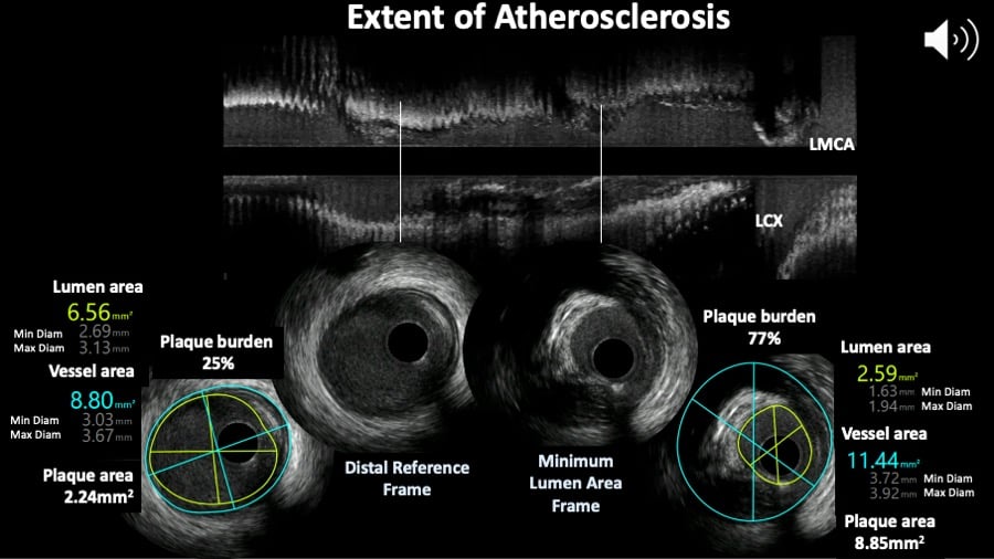
Figure 7
Extent of atherosclerosis assessed by intravascular ultrasound. The top panel shows the longitunal view and two cross sections showing the minimum lumen area frame and reference site.
ASSESSMENT OF ATHEROMA BURDEN
The quantification of atheroma or plaque area in cross sectional IVUS images is performed by subtracting the lumen area from the EEL area (also known as vessel area). Hence, IVUS-defined atheroma area is a combination of plaque plus media area.
The consensus document on IVUS defines plaque (or atheroma) burden as follows : Plaque plus media area divided by the vessel area. From the video example, the plaque (plus media) is the difference between vessel minus lumen areas in both frames and plaque burden is for the distal reference frame 2.24 divided by 8.8 times 100 equals 25% and for the MLA frame plaque burden is 77% following the same calculation.
The plaque area can be then be calculated in each frame (cross-sectional image), and total atheroma volume (TAV) can be calculated based on pullback speed during imaging acquisition. Atheroma volume can be reported as the percentage of the volume of the external elastic membrane occupied by atheroma, namely percentage atheroma volume (PAV). Parameters commonly used to report the extent of the coronary atherosclerosis are shown in Figure 8.
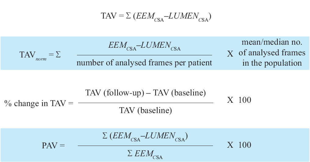
Figure 8
Variables measured in progression/regression longitudinal IVUS studies. TAV is total atheroma value ; EEM is external elastic membrane ; PAV is percentage atheroma value.
LEFT MAIN CORONARY DISEASE
The left main coronary artery (LMCA) is a very challenging anatomical segment to evaluate since the ostium has an oval and angled shape, it has a curved course, when present coronary artery is diffuse and extends into the LAD and LCX. The take off angle of these two vessels is variable and there may be a third « intermediate » branch. These reasons make the angiographic evaluation of the LMCA difficult and incomplete and therefore IVUS plays an esential role not only in making the diagnosis of the extent of the disease, but also helps to inform the planning of a revascularisation strategy. IVUS acquisition often requires disengaging of the guide catheter to evaluate the ostium and the need to perform two pullbacks, one from the LAD and a second from the LCX as the mimimum lumen area assessments in the LMCA may vary depending of the coaxiality of the IVUS probe within the vessel. A oblique cathether position can create an artificially large MLA, but not one that is artificially small; therefore, the smallest MLA from the two pullbacks is the most accurate.
There is no absolute consensus regarding the CSA at which a left main obstruction is considered critical. A study evaluating IVUS assessment of 121 patients with intermediate LM lesions found no significant difference in MACE (death, non-fatal MI and TVR) after 3 years of follow up between patients with MLA<7.5 mm2 who underwent revascularisation and those with MLA>7.5 mm2 in whom revascularisation was deferred (21% vs. 12%). By contrast, patients with MLA<7.5 mm2 who did not undergo revascularisation had a 3-year MACE rate of 50% . In another study, an IVUS-determined MLD of 2.8 mm and an MLA of 5.9 mm2 had the highest sensitivity and specificity (93% and 98% for MLD, 93% and 95% for MLA respectively) for detecting haemodynamic significant left main stenosis compared with FFR . In a prospective multicentre Spanish cohort (LITRO study) involving 354 patients with borderline unprotected left main disease on angiography, the IVUS cut-off criteria of a minimal lumen area > 6 mm2 was used to defer revascularisation. The 179 patients eventually not revascularised based on this criterion had a 94% MACE-free survival at 2 years An expert consensus document of the European Association of Percutaneous Cardiovascular Interventions recommends to defer LMCA revascularization if the MLA > 6 mm2, to intervene if the MLA < 4.5 mm2 and to consider further evaluation with FFR if the MLA is between 4.5 and 6 mm2. (Figure 9A and Figure 9B). (Video LM pearl).
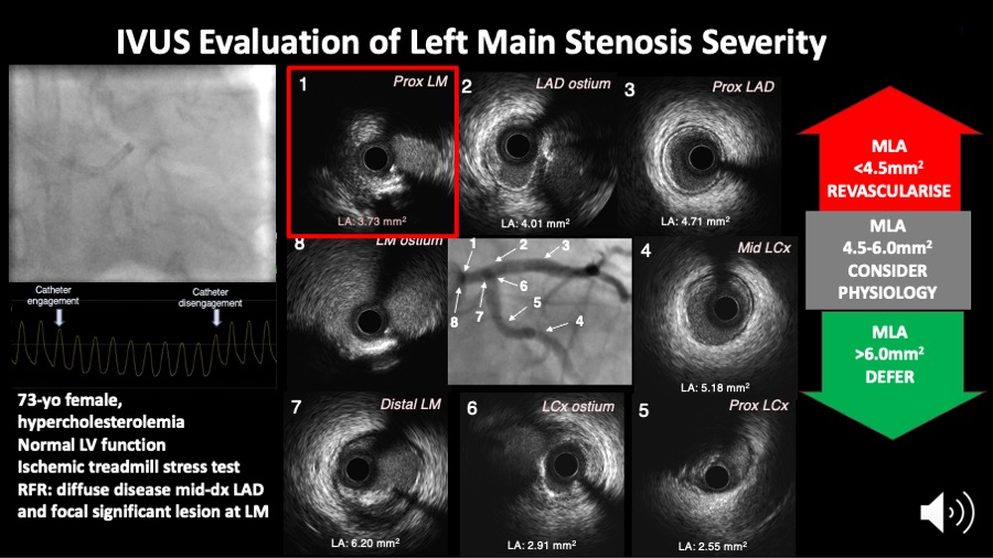
Figure 9A
Figure 9A shows the IVUS assessment of a left main coronary artery stenosis. IVUS helps to measure the minimum lumen area which may inform the need for revascularisation as per the scheme on the right side of the figure.
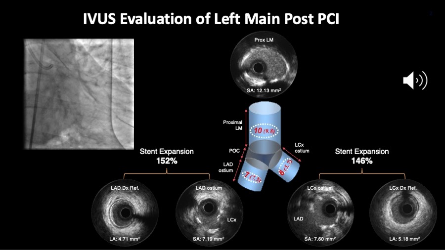
Figure 9B
Figure 9B shows the angiography and IVUS results after the stenting. Important to check whether the proposed cut off values for minimum stent area in each segment are achieved. Alternatively, one can also look at the relative expansion index.
Angiography and IVUS images are courtesy of Daniel Chamie.
Video LM pearl
Percutaneous coronary intervention is increasingly being used in the left main coronary artery and ESC guidelines on coronary revascularisation indicate a class IIa recommendation for PCI in anatomically non-complex unprotected left main disease . Optimising DES results appears to be especially important in this setting since DES failures, particularly stent thrombosis, may have devastating consequences. In the left main, IVUS may visualise stent protrusion into the aortic root, underexpansion (noting that this coronary segment is frequently calcified), malapposition and significant jailing of the circumflex coronary artery . When complex two stent techniques (V or T stents, crushing, kissing stents) are performed, IVUS is required to ensure optimal final results.
In the MAIN-COMPARE registry, Park et al have shown that elective DES implantation in unprotected left main disease with IVUS guidance alone may reduce longterm mortality when compared with conventional angiography guidance. Patients with unprotected left main coronary artery stenosis in haemodynamically stable conditions underwent elective stenting under the guidance of IVUS (756 patients) or conventional angiography (219 patients). The study was not randomised but propensity score analyses were used to adjust for potential confounders between the two groups. After adjustment, the 3-year incidence of mortality was lower with IVUS guidance as compared to angiography guidance (4.7% versus 16.0%, p=0.048). This study is interesting and indeed provocative but criteria for optimal stent expansion in the left main were not clarified .
Two randomized controlled trials reported mortality advantages associated with IVUS-guided left main coronary artery (LMCA) DES implantation, the largest , enrolling 336 patients showed that after 1-year of follow-up, the MACE rate was significantly lower in the IVUS-guided than in the angiography-guided group (13.2% vs 21.9%; P = .031), mainly from a reduction in cardiac death (1.8% vs 5.9%; P = .048). Reduction in all-cause and cardiovascular mortality has been also confirmed in five meta-analyses. IVUS guidance significantly reduced MACE in all of them.
More left main studies are ongoing, see Table 2.
Table 2. Ongoing complex PCI and left main coronary artery studies.
| Patient/Lesion Characteristics Included In Ongoing IVUS-Guided PCI Studies | ||||||||
|---|---|---|---|---|---|---|---|---|
| Left Main Coronary Artery (LMCA) | Bifurcation Lesions | Chronic Total Occlusions | In Stent Restenosis | Calcified Lesions | Long Lesions | Special Considerations | Imaging Criteria | |
| IMPROVE trial (NCT04221815) | Protected LMCA only (any type of anatomy) | Any Medina class that involves any coronary main branch disease with a side branch ≥2.0 mm | Any | Any | Severe | ≥28 mm in length | Excluded |
Optimal stent deployment is considered to have been achieved if on final IVUS the following 3 criteria have been met:
|
| IVUS CHIP trial (NCT04854070) | Any | True bifurcation lesions involving side-branches >2.5mm | Any | Any | Severe | ≥28 mm in length | Ostial lesions & need for elective mechanical circulatory support assisted PCI |
|
| OPTIMAL trial (NCT04111770) | De novo lesion of the LM (ostial, shaft or distal) where PCI is approved by the Heart Team* | Any left-main Medina classification 100, 110, 101, 011, 010, 111, 001 (left-main equivalent) can be included. | Not included | Not included | Not included | Not included | Not included |
|
OSTIAL AND BIFURCATION DISEASE
Bifurcation lesions (old) and Ostial lesions and Left main coronary artery disease (old)
The continuous dynamic variation in the three-dimensional anatomical configurations of coronary bifurcations poses significant challenges to planar coronary imaging modalities. Intravascular imaging plays an important role in evaluating severity and distribution of atheroma in the bifurcation segment.
The in vivo frequency and distribution of high-risk plaques (i.e., necrotic core rich) at bifurcations using a combined plaque assessment with IVUS virtual histology and optical coherence tomography has been reported. A total of 30 patients (103 bifurcations) were imaged. 27 fibroatheromas (26.2%) and 18 thin-cap fibroatheromas (17.4%) were found. Overall, the percentage of necrotic core decreases from proximal to distal rim (16.8% vs. 13.5% respectively, p=0.01) while the cap thickness showed an inverse tendency (130±105 vs. 151±68μm for proximal and distal rim respectively, p=0.05); 44.1% of the thin caps were located in the proximal rim, 41.2% followed the in-bifurcation segment and were less frequent in the distal rim (14.7%). The proximal rim of the ostium of the side branch has been identified as a region more likely to contain thin fibrous cap and a greater proportion of necrotic core . In addition, bifurcation lesions appear to have a larger plaque burden with a different plaque composition compared to non-bifurcation lesions as assessed by IVUS virtual histology . This may partly explain the adverse outcomes seen following treatment of bifurcation lesions in contemporary practice.
There has been proposed that IVUS can help to better characterise the complexity of the disease especially when MEDINA is 1,1,1; 1,0,1; 0,1,1 plus one of the following findings :
1. SB disease length ≥10 mm ; 2.Thrombotic lesion ; 3. Calcium arc >60° at the culprit lesion site ; 4.• Difficult SB access (higher risk if bifurcation angle A <90°)
After stenting, IVUS can help to optimize stenting results by quantifying the stent expansion index, which in case of bifurcation has to be calculated twice, one for the proximal main branch segment using minimum stent area (MSA) divided by the proximal reference lumen area and the second for the distal main branch segment for which the MSA should be found within that segment and divide it by the distal reference lumen area.
CARDIAC ALLOGRAFT DISEASE
Most adverse clinical events in transplanted patients occur after 1 year. According to data from an observational study, the cumulative incidence of cardiac events per patient year was 0.9% within the first year, increasing to 1.9% by 5 years. Cardiac events accounted for 3.8% of the deaths by the end of the first year, rising to 18% of total mortality by 7 years after heart transplantation. After the first year of transplantation, 36% (20/55) of the patients died following sequelae of coronary artery disease . Myocardial infarction is usually silent because the heart is denervated. Based upon such data there is a need for screening, mostly using IVUS, in order to detect coronary atherosclerosis at an early stage. The presence of obstructive coronary disease on angiography is a predictor of any cardiac event (odds ratio 3.44, p<0.05), as well as a predictor of cardiac death (OR 4.6, p< 0.05).
However, a pathological study has reported on 10 patients who died or underwent re-transplantation within 2 months of coronary angiography. One quarter of the patients had intermediate lesions or atheromatous plaques. Fresh or organising thrombus was most often associated with discrete lesions and accounted for all complete occlusions. The authors concluded that transplant coronary artery disease has a heterogeneous histological and angiographic appearance, with angiographic underestimation of disease in some patients. Accordingly, many active transplant centres incorporate IVUS imaging into their post-transplant surveillance, but there is no consensus on how frequent IVUS should be performed. The predictive value of IVUS has been explored in a study that included 143 patients who underwent 3-vessel IVUS investigation at 1 and 12 months after transplantation. The change in intimal thickness was calculated (≥0.5 mm was defined as rapidly progressive vasculopathy). At one year, rapid progression was demonstrated in 37% of the patients and in 47% of them a new lesion was found. At 5.9 years, patients with rapid progression died more than their counterparts (26% vs. 11%, p = 0.03). The combined endpoint of death and MI was also more frequently seen in patients with rapid progression (51% vs. 16%, p < 0.0001) .
IVUS has also been used to assess novel therapies in heart transplantation recipients. Eisen et al randomised 634 patients to receive 1.5 mg of everolimus per day (209 patients), 3.0 mg of everolimus per day (211 patients), or 1.0 to 3.0 mg of azathioprine per kilogram of body weight per day (214 patients), in combination with cyclosporin, corticosteroids and statins. The primary efficacy endpoint was a composite of death, graft loss or re-transplantation, loss to follow-up, biopsy-proved acute rejection of grade 3A, or rejection with haemodynamic compromise. At 1 year, IVUS showed that the average increase in maximal intimal thickness was significantly smaller in the two everolimus groups than in the azathioprine group .
Clinical applications: interventional
The use of intravascular imaging to guide percutaneous coronary interventions is heterogeneously distributed across the world, varying from >60% of use during PCI in Japan to less than 20% in Europe and the United States. The explanation for such disparity is multi-factorial but probably involves local reimbursement practices for the procedure, differences in clinical practice and training, and a relative lack of scientific evidence.
Intravascular ultrasound imaging provides an accurate means to determine vessel size, severity, character, extent, and location of disease and guide therapeutic decision-making in the catheterisation laboratory. The additional information provided by IVUS on lesion composition, eccentricity and length may change treatment strategies in up to 20% of cases . As discussed previously, the presence, depth and circumferential distribution of calcification are very important factors for selecting the type of interventional device .
NON-STENT BASED PERCUTANEOUS CORONARY INTERVENTIONS
Contemporary PCI techniques are essentially based on stents, but balloon angioplasty remains an integral part of the procedure. In addition, atherectomy and plaque modification strategies (i.e cutting and scoring balloons and intravascular lithotrypsy - IVL) are necessary in some procedures. Thus, understanding of mechanisms and the proper utilisation of these techniques remains important in the modern era . The importance of intravascular imaging is likely to be amplified in non-stent-based interventions with the goal of maximal luminal gain and minimal risk of dissection and vessel perforation. Selection of the device size can be based on measurements of the total vessel (i.e., EEM) diameter, although a more conservative approach matching balloon size to that of lumen diameter of the distal reference segments is in practice most routinely performed.
Modifications of the dilatation strategy based on IVUS results include changes in balloon diameter, length, type and inflation pressure. IVUS is also critical to define circumferential and longitudinal extension of plaque fracture or dissection, and to guide the need for further intervention. Dissections (see also a separate section on dissections below) can be classified into five categories:
- intimal;
- medial;
- adventitial;
- intramural haematoma (an accumulation of blood within the medial space, displacing the internal elastic membrane inward and EEM outward); and
- intra-stent .
The severity of a dissection can be quantified according to:
- depth;
- circumferential extent (in degrees of arc);
- length;
- size of residual lumen (CSA); and 5. CSA of the luminal dissection.
Additional descriptors of a dissection may include the presence of a false lumen, the identification of mobile flap(s), the presence of calcium at the dissection border, and dissections in close proximity to stent edges.
IVUS studies have also been performed to define predictors of restenosis after plain balloon angioplasty (POBA). One of the main contributions to this field was the realisation that negative remodelling, not neointimal hyperplasia, was the most important mechanism of long-term failures of non-stented coronary interventions, namely restenosis. This was initially demonstrated in the peripheral vessels and later reported in the coronary circulation. These studies revealed that >70% of lumen loss was attributable to the decrease in EEM area, whereas the neointimal area accounted for only 23% of the loss. Whether these lessons learned in the POBA studies would have any implications in the ongoing drug coated balloon (DCB) studies remains to be seen. In general, drug-coated balloons have been introduced as a therapeutic strategy (mainly for patients with in-stent restenosis) and IVUS may also be of practical value for the optimisation of balloon sizing. Large de novo lesions DCBs studies would provide information about their role in this lesion subset.
IVUS has been used to understand the mechanism of action of cutting balloon angioplasty, a technique, which may be used in selected cases to optimise initial results. Similarly, evaluating the mechanism of IVL using IVUS showed that there was an increase in MLA from pre-IVL to post-IVL treatment to post-stenting was successfully achieved by « fracturing » the calcium (Video Calcium and IVL).
Video Calcium and IVL
STENT-BASED PERCUTANEOUS CORONARY INTERVENTIONS
IVUS has played a critical role in the establishment of modern stent deployment technique. IVUS provides cross-sectional views of the stent and its interaction with the vessel wall enabling unique assessment of expansion, apposition, vessel dissection and residual untreated disease which cannot be properly defined by angiography. The pioneering report of Colombo and co-workers revealing a mean residual stenosis of 51% following angiography guided stent deployment and a high prevalence of incomplete stent apposition significantly altered the understanding of optimal stent deployment and prevention of subacute thrombosis . After balloon inflations at higher pressures (typically 18–20 atm), use of a larger balloon, or both, the operators were able to reduce the residual stenosis to 34%, which most likely explained a 0.3% rate of subacute thrombosis without the need for systemic post-procedure anticoagulation . However, restenosis remained an important limitation of bare metal stents affecting approximately 20% to 40% of patients.
“The bigger, the better” adage which has dominated the interventional cardiology approach for decades derived from angiographic assessment of lumen gain and late loss, but it also underlines the importance of IVUS to optimise stent expansion and maximise lumen gain without the risk of vascular complication. The landmark MUSIC study defined IVUS criteria for optimal stenting. It was based on 3 variables:
- complete apposition of the stent over its entire length;
- symmetrical stent expansion defined by the ratio of minimal/ maximal lumen diameter ≥0.7; and
- in-stent minimal lumen area ≥90% of the average area of distal and proximal references or ≥100% of the lumen area of the reference segment with the smallest lumen area.
The subgroup of patients who met the criteria had a record 8% rate of restenosis after bare metal stent implantation. However, the criteria are difficult to achieve in real practice. More recent studies which used DES such as the impact of Intravascular Ultrasound Guidance on Outcomes of Xience Prime Stents in Long Lesions - IVUS-XPL randomized trial found that the patients within the IVUS-guided stent group, the patients who did not meet the IVUS criteria had a significantly higher incidence of the primary end point compared with those meeting the IVUS criteria for stent optimization (4.6% vs 1.5%, respectively; HR, 0.31 [95% CI, 0.11-0.86], P = .02.
Routine IVUS-guided DES optimisation is therefore attractive. In Figure 10A and Figure 10B, the pre-PCI CALL-Di and post-PCI DIAL-X approach are shown. These are nemonics to help remember the actionable IVUS elements that may inform clinical decisions. It should be acknowledged, however, that this approach requires a learning curve to ensure adequate interpretation and implementation during routine clinical practice (Video CALLD DIAL X).
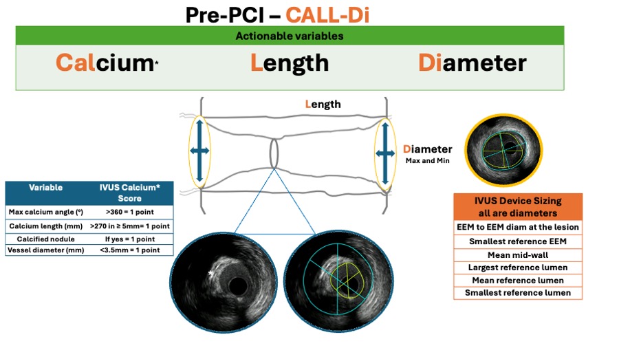
Figure 10A
IVUS helps to guide the PCI following a systematic approach. In the pre-PCI phase (figure 10A), the CALL-Di workflow should be executed to ensure that no relevant and actional information is overlooked.
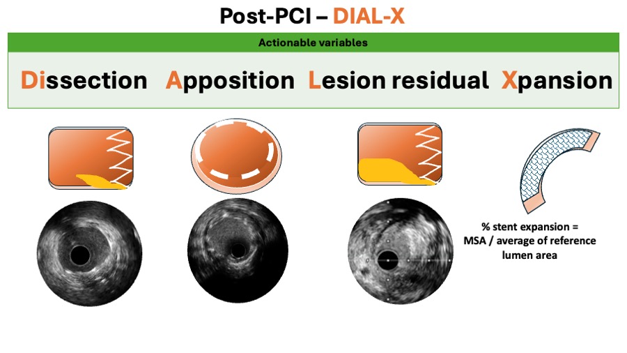
Figure 10B
Similarly, in the post PCI phase (figure 10B), the DIAL-X workflow should be followed.
Video CALLD DIAL X
The focus of contemporary interventional cardiology has shifted towards improving the safety rather than the efficacy of DES, as these devices dramatically reduced the problem of restenosis.
A metaanalysis report included 6856 patients from 12 randomised trials and showed that for the comparison of intravascular ultrasound versus angiography guidance in terms of target lesion failure (TLF), IVUS guidance reduced TLF significantly by 34%, mostly at expenses of reducing cardiac death by 44% and TLR by 35%. (Figure 11A, Figure 11B, Figure 11C and Figure 11D).
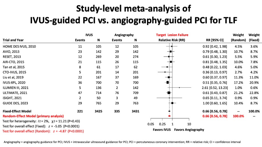
Figure 11A
A network metanalysis reported for the comparision between IVUS- and angio-guided PCI, the target lesion failure (figure 11A) composite endpoint was significantly reduced.
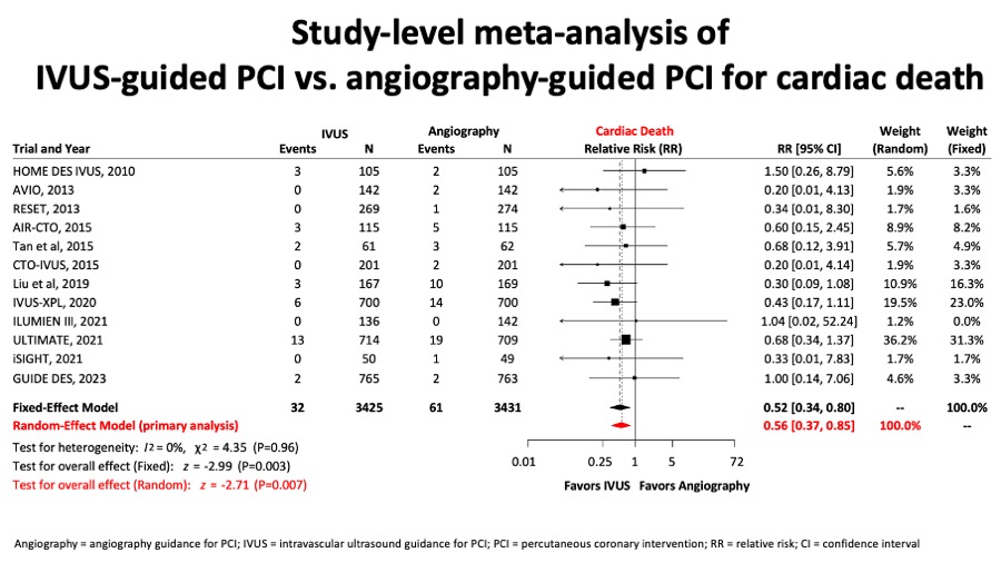
Figure 11B
Similarly, in figure 11B, a important reduction in cardiac death in the group of IVUS-guided PCI was observed.
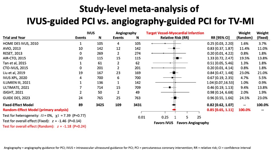
Figure 11C
There was no difference in terms of target vessel myocardial infarction (figure 11C).
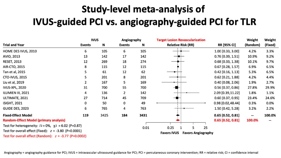
Figure 11D
Conversely, there was a clinically relevant and significant reduction of target lesion revascularisation rates in the IVUS-guided PCI group (figure 11D).
IVUS guidance has been advocated particularly in selected high-risk lesions The main use of IVUS guidance in LM PCI is to optimize stenting results which are associated with reduced MACE in the follow-up. This has been confirmed in the reports from the British Cardiovascular Intervention Society and from a substudy from the NOBLE trial (drug-eluting stents [DES] vs bypass surgery in patients with LMCA disease) , . Particularly, in the NOBLE study, the larger the MSA, the lower the rate of revascularization. Another study using a specific protocol with optimisation targets for IVUS-guided left main revascularisation comparing vs. both an IVUS guidance without a pre-specified protocol and an angiography guidance alone groups, patients treated with the pre-specified protocol achieved higher stent expansion rates. Further, compared to angiography guidance, the IVUS protocol group had better clinical outcomes .
Diseased bypass grafts have been a challenge for both interventionists and cardiac surgeons and deserve a separate discussion. The treatment of this subset of patients represents about 5% to 10% of cases in the catheter laboratory. Although the use of DES in saphenous vein graft reduces both TVR and TLR, and are proven to be safe , intravascular imaging is important to guide stent size selection and to define the extent of disease. In addition, IVUS has also been used to monitor outcomes after treatment of vein grafts with DES. The SECURE study included 76 patients (n = 94 lesions) with graft disease treated with a sirolimus-eluting stent, and 14 patients had IVUS follow-up performed at 8 months. Overall, the percentage of intimal hyperplasia was 11.8 ± 16.5% and half of the patients with graft sirolimus-eluting stent had < 1% intimal hyperplasia . In the setting of a randomised trial, 75 patients with graft disease (96 lesions) who received either sirolimus-eluting stents or bare metal stents (RRISC study) were assessed by IVUS at 6 months. Sirolimus-eluting stents showed smaller neointimal hyperplasia volume compared with BMSs (1.3 vs. 24.5 mm3, p<0.001). In the sirolimus-eluting stent group, there was a greater intimal hyperplasia at overlapping sites as compared to non-overlapping segments .
Coming up, the IMPact on Revascularization Outcomes of intraVascular Ultrasound Guided Treatment of Complex Lesions and Economic Impact (IMPROVE - NCT04221815) trial will include patients from Europe and Northamerica. The primary endpoint is target vessel failure outcomes at 12 months defined as the composite of cardiac death, target vessel related-myocardial infarction, and ischemia-driven target vessel revascularization.. Another IVUS trials are also awaited : CHIP trial (NCT04854070) and the OPTIMAL trial, NCT04111770. Table 2.
Assessment of complications after percutaneous coronary interventions
THROMBOSIS
IVUS provides a unique tool to visualise the underlying mechanical factors involved in stent thrombosis , . Dedicated studies have been reported in which the use of IVUS is central during index PCI in order to prevent a future stent thrombosis. The Assessment of Dual Antiplatelet Therapy With Drug-Eluting Stents (ADAPT-DES) was a nonrandomized "all-comers" study of 8583 consecutive patients aiming at characterizing the frequency, timing, and correlates of stent thrombosis and adverse clinical events after DES. IVUS guidance compared with angiography guidance reduced definite/probable stent thrombosis (0.6% [18 events] versus 1.0% [53 events]; adjusted hazard radio, 0.40; 95% confidence interval, 0.21-0.73; P=0.003), myocardial infarction (2.5% versus 3.7%; adjusted hazard radio, 0.66; 95% confidence interval, 0.49-0.88; P=0.004), and composite adjudicated major adverse cardiac events (ie, cardiac death, myocardial infarction, or stent thrombosis) (3.1% versus 4.7%; adjusted hazard radio, 0.70; 95% confidence interval, 0.55-0.88; P=0.002) at 1-year.
In the DES era, severe stent underexpansion appears to be the most important factor affecting most patients suffering from this catastrophic complication , , . Residual plaque at the edges of the stent has also been detected in most cases . However, residual edge dissections appear to be a more important aetiological factor for stent thrombosis after BMS than after SES implantation . As previously discussed, the role of stent malapposition is more controversial. When patients with late incomplete malapposition are followed up, most of them have an uncomplicated clinical course even in the absence of dual antiplatelet therapy. However, when patients suffering episodes of DES thrombosis are examined during the acute episode, half of them show incomplete stent apposition over relatively large areas (Figure 10B).
The use of IVUS is highly recommended during coronary interventions performed to treat episodes of stent thrombosis. In a previous study, patients suffering episodes of DES thrombosis were imaged using 3-D IVUS findings. An occlusive thrombus within the stent (50% of total stent volume) was recognised in all patients. Most DES had severe underexpansion and all patients had inflow-outflow disease. Notably, malapposition was detected in 50% of cases. A major side branch jailed by the stent struts was present in 67% of cases. Classic optimal criteria for stent deployment were not seen in any patient. Following interventions using IVUS-guided large balloons or higher pressures, stent expansion improved (minimum stent area 9+3 vs. 12+4 mm2, p<0.08) and malappositon was resolved in all cases. However, 17% of total stent volume was occupied by residual resistant lining thrombus . In the study by Cook et al , incomplete apposition was visualised in 77% of patients suffering from very late DES thrombosis.
Most studies suggest that, despite early and aggressive treatment, stent thromboses have dreadful consequences leading to large Q-wave myocardial infarctions and a high mortality rate (from 17% to 45%) . The large thrombus burden present in most cases of stent thrombosis explains the poorer clinical outcome compared with other patients requiring primary angioplasty. IVUS should always be used to identify any potential mechanical predisposing factors and to ensure an optimal final result. Whenever possible, implantation of a new stent to improve a suboptimal result should be avoided. In most of these cases, the underlying mechanism will be a resistant thrombus and aggressive pharmacological therapy may cause disappearance of residual thrombus within 1 week . It is important to keep in mind that, in addition to addressing mechanical factors, functional studies on platelet reactivity may also be indicated . In 2 prospective intravascular ultrasound studies of patients treated with primary angioplasty for episodes of stent thrombosis, it has been found that despite all the optimisation efforts (IVUS-guided high pressure balloon inflations and systematic intracoronary administration of glycoprotein IIb/IIIa platelet inhibitors and routine use of thrombectomy devices), there was a significant amount of residual “resistant” thrombus within the stent at the end of the procedure , . This residual thrombus detected by IVUS appears to explain why suboptimal angiographic results are frequently obtained despite aggressive interventions .
RESTENOSIS
DES in-stent restenosis represents the most frequent cause of DES failure , .Unlike restenosis after balloon angioplasty or atherectomy, IVUS studies have shown that in-stent restenosis is essentially a result of neointimal hyperplasia IVUS predictors of stent restenosis have been identified by multivariate analyses and include small reference vessel and lumen size, the larger plaque burden, and small in-stent lumen area. While the prevalence of restenosis has decreased dramatically with DES, maximising luminal gain remains an important approach to prevent restenosis. Receiver operating characteristic curves identified post-stenting minimum stent CSA of 5 mm2 for sirolimus-eluting stent and 6.5 mm2 for bare metal stents were associated with lumen CSA > 4 mm2 at 8-month follow-up 120. Others have shown that the highest restenosis rate was observed in lesions with stent area <5.5 mm2 and stent length >40 mm after deployment of sirolimus-eluting stents .
Intravascular imaging is also essential to guide therapy of in-stent restenosis as mechanical problems related to stent deployment procedures contribute to approximately 25% of cases with in-stent restenosis . Stent fracture has been reported as a rare cause of stent restenosis in the modern era of long stent implantation, which can be identified by intravascular imaging. This is discussed in more detail below.
Furthermore, while diffuse in-stent restenosis is common after bare metal stents, a focal pattern of restenosis is most frequently associated with DES. One of the most common variables used to report restenosis is percentage intimal hyperplasia volume in the stent segment . This variable normalises the intimal hyperplasia to the stent length therefore allowing the comparison of different stent types (BMS vs. DES), as well as different drug types (i.e., sirolimus-eluting stent –SES- vs. paclitaxel-eluting stent –PES-). Intravascular imaging has shown that characteristics of neointimal hyperplasia may differ between bare metal stents and DES. Neointimal hyperplasia in DES may have an echolucent appearance, also known as a black hole .
However, this parameter (the percentage intimal hyperplasia) minimises the impact of focal restenosis. A meta-analysis of TAXUS IV, V and VI demonstrated that nearly half of the stent length was free of intimal hyperplasia in the Taxus group (48.8 ± 36.0% vs. 13.4 ± 22.1% in the control group, p <0.0001) . In another study comparing the paclitaxel stent and the sirolimus stent, 46.1 vs. 5.4%, respectively, of the stent length had covering, p < 0.001 . It has been suggested that the patchy distribution of intimal growth associated with DES (i.e., lack of neointimal tissue in the mid portion of the stent) could be related to a higher concentration of drug in that portion of the stent .
Currently DES are considered the treatment of choice for BMS in-stent restenosis , . A 3-D volumetric IVUS substudy of the RIBS II randomised trial suggested that DES almost completely abolished recurrent neointimal proliferation in these patients, whereas balloon angioplasty was shadowed by significant neointimal proliferation at late follow-up .
DES in-stent restenoses are rare but, when they occur, they are more difficult to treat and they had a higher rate of recurrence than BMS in-stent restenosis . Therefore, optimisation of the repeated treatment seems mandatory . ESC/EACTS Guidelines on myocardial revascularization recommend to use IVUS to detect the underlying mechanical cause of restenosis.
In terms of angiography, DES in-stent restenosis differs from BMS in-stent restenosis in that most DES in-stent restenoses are focal (length <10 mm) and are frequently located at the stent edges (more frequently after SES than after PES) . As in BMS in-stent restenosis, diffuse patterns are associated with a poorer prognosis . The problems of remodelling at the edges, geographical miss and the “candy wrapper’’ phenomenon have been addressed previously . IVUS allows precise stent visualisation which is critical: firstly, to assess the mechanisms of DES in-stent restenosis; and secondly to guide repeated interventions. IVUS is also a useful tool for excluding jailing of major related side branches and DES protrusion at the ostia . Severe DES underexpansion is the most common underlying substrate and this problem appears to bear more important pathophysiological consequences than when detected in patients with BMS in-stent restenosis . In cases with severe underexpansion, every effort should be made to resolve this situation. However, some underexpanded DES are located in heavily calcified coronary segments (napkin ring image) and, once the stent is under-deployed, very little can be done to improve the situation . In this challenging scenario very high pressures (24 to 30 atm) are recommended before repeated DES implantation in an attempt to avoid perpetuating the problem. Conversely, when the stent is well expanded, the underlying mechanism may be drug failure . In this setting, some investigators suggest switching to another DES with a different drug although this approach remains largely empirical . Although IVUS optimisation of the repeated intervention is considered as mandatory by most investigators, specific guidelines in this regard are lacking. DES represents the strategy of choice for DES in-stent restenosis. Recently, however, the use of paclitaxel-eluting balloon is emerging as a promising new therapy . IVUS findings after this novel approach remain to be determined.
PLAQUE AT THE STENT EDGES
IVUS can be used to detect problems at the stent edges. After interventions, angiographic “haziness” at the stent edges may be the result of thrombus, plaque shift or dissections. At follow-up, the mechanisms of edge in-stent restenosis may be uncovered. During DES implantation, geographic miss should be avoided because this problem may lead to a “candy wrapper” effect . Sakurai et al demonstrated that larger reference plaque burdens and large edge stent cross-sectional areas/reference vessel lumen areas, were associated with SES in-stent restenosis. These investigators suggested that incomplete lesion coverage - as the result of landing the stent edge on an atheromatous plaque - was a risk factor for the subsequent development of edge in-stent restenosis. In the DIABETES trial , volumetric IVUS analyses of the stent edges demonstrated that after SES implantation the increase in external elastic membrane volume was greater than the increase in plaque volume, thus resulting in a net lumen gain. Finally, Jensen et al compared peri-stent remodelling and proximal and distal edge effects after SES and PES in patients with diabetes mellitus.
CORONARY DISSECTIONS
In the BMS era, there was a tendency to avoid stenting long coronary segments even if some residual dissections were detected at the distal end. The fear of restenosis associated with long stented segments was high at that time. The sealing of the dissection entry point with the stent appeared to be sufficient. Although most residual nonocclusive residual dissections have a good outcome and, in fact, disappear at follow-up, some of them may be responsible for major events such as thrombosis or restenosis. These tend to disappear at late follow-up IVUS studies. An IVUS lumen cross-sectional area >4.5 mm2 or 70% of the reference vessel lumen area is considered a reliable indicator that the index dissection is not likely to bear adverse consequences . IVUS thus plays an important role in defining the management of dissections.
The RECIPE DES registry found, angiographically detected residual edge-dissections in 1.7% of lesions (71% types A/B, 80% normal coronary flow) treated with PCI. Coronary calcification and diffuse disease were predictors of dissections. In this study, residual dissections after DES were associated with adverse prognosis 144. Of interest, a surprisingly high number of dissections (up to 37%) persisted at late angiographic follow-up. This leaves open the possibility that the drug released by the DES played a role in preventing vessel healing .
Lemos et al suggested that edge restenosis after DES may occur at sites with residual dissections. The DIABETES trial 135 demonstrated similar rates of persistent and resolved edge-related dissections after SES and BMS. In an interesting study, Liu et al analysed edge dissections in 1,045 DES implanted in 887 patients. A total of 82 dissections (9.2%) were detected, equally distributed between the proximal and distal edges. Many of these dissections (39%) were not detected by angiography. Large residual plaques and calcified lesions were more frequently found in DES with edge dissections. Residual plaque eccentricity, lumen-to-stent-edge area ratio and stent-edge asymmetry predicted edge dissections after DES. An evolution to intramural haematoma was more frequently detected in dissections located in less diseased segments, where haematoma formation and expansion tend to occur. It remains to be determined whether healing and endothelialisation after DES are possibly impaired and thus dissection sealing delayed, as compared with dissections detected after BMS implantation .
PLAQUE PROLAPSE
Plaque prolapse from the stent struts into the lumen may be readily recognised with IVUS. Prolapse may be the result of protruding soft plaque, disrupted fibrous plaque, confined minor dissections or even thrombus. Differentiation between plaque and thrombus may be difficult even with the use of IVUS. The presence of wide stent strut gaps due to stent characteristics or strut distortion, a large burden of soft atheromatous plaque or thrombus, and aggressive dilations resulting in overexpanded stents may all result in plaque prolapse . Plaque prolapse may be suspected with angiography but only IVUS confirms the diagnosis. Due to its higher resolution (15 microns), OCT provides a more accurate visualisation of very small amounts of plaque prolapse but the clinical implications of plaque prolapse not identified by IVUS still remain unclear.
Plaque prolapse appears to be particularly prevalent during primary angioplasty. In the HORIZONS-AMI study , plaque or thrombus protrusion through the stent struts was initially present in 70% of PES and 65% of BMS but all of these resolved during follow-up and clinical consequences were not observed. Kim et al used IVUS to evaluate incidence, characteristics and clinical consequences of plaque prolapse after DES implantation. DES were serially expanded, first at 14 atm and then at 20 atm, in 80 patients. At 14 atm occurrence of plaque prolapse was 41% after SES and 24% after PES. At 20 atm incidence and characteristics of plaque prolapse did not change. Lesions developing prolapse were longer, had less superficial calcium, lower lumen cross-sectional area and larger plaque burden and remodelling index than lesions without prolapse. In addition, CK-MB elevation was higher in lesions with plaque prolapse. In another interesting IVUS study evaluating this issue in patients with diabetes, plaque prolapse was more frequent in severe stenosis, chronic total occlusions and in the right coronary artery. However, neointimal proliferation and thrombosis risk was similar in stents with and without plaque prolapse. Therefore, the authors concluded that presence of plaque prolapse after DES implantation does not warrant further interventional manoeuvres.
STENT FRACTURE
Stent fracture has been identified as a rare but important underlying cause of DES failure . This complication, however, is difficult to recognise on conventional angiography due to the poor stent visualisation. IVUS allows precise stent strut visualisation and has therefore been used to detect stent fractures. On angiography, stent fractures are suspected in the presence of a lack of continuity of the stent struts. On IVUS “complete” fractures are visualised as total separation of the stent into >2 parts: at this point, image frames with no struts should be clearly detected. The IVUS diagnosis of “partial” fractures is more challenging, if not impossible, and usually requires the absence of struts over a significant arc of stent circumference. Similar findings in segments with overlapping stents should not be considered as fractures but rather as stent displacement. Unexpected gaps between adjacent contiguous DES which were believed to be overlapped are frequently detected during follow-up IVUS studies. Obviously, this represents a major stimulus for focal in-stent restenosis.
Predictors for stent fracture include right coronary artery location, long stents, overlapped stents, hinge movements and vessel angulation .
Doi et al reported 20 cases of IVUS-detected stent strut fractures in 17 patients. Of these 18 (90%) occurred in SES whereas only 2 (10%) were detected in BMS. No fractures were detected in PES. Half of the fractures were considered complete and the rest were just partial fractures (mean maximum inter-strut angle of 218º). Interestingly enough, 5 of the 20 stent fractures were accompanied by coronary aneurysm formation (all complete fractures in SES) and 2 were associated with very late stent thrombosis. Fractures occurred in long stented segments. These investigators proposed that “early” fractures may be the result of hinge movement at calcified sites whereas “late’’ fractures may be associated with coronary aneurysm formation.
INCOMPLETE STENT APPOSITION
Adequate stent contact (apposition) against the vessel wall is important to obtain good rheological conditions and adequate stent endothelialisation. In the DES era, full apposition of the stent struts against the underlying atheromatous plaque is required to ensure adequate drug delivery. (Figure 10B)
In some cases, however, such as lesions with uneven calcified plaques, ulcerated plaques, ostial lesions or lesions located at the edges of naturally occurring aneurysms, complete apposition remains impossible to achieve , . Stent conformability, flexibility and stent structure may also be important. Angiography is unable to recognise incomplete apposition because contrast medium enters the area behind the malapposed stent, yielding in most cases an optimal angiographic appearance. IVUS, however, can identify and provide a unique opportunity to study this phenomenon and its temporal changes. Incomplete apposition is defined by and occurs when at least 1 stent strut (not encompassing the origin of a side branch) is not in direct contact with the underlying vessel wall. Incomplete stent apposition may be acute or late. Acute incomplete apposition essentially represents suboptimal stent deployment and may resolve at follow-up as the result of thrombus accumulation, plaque growth or negative remodelling, or all of these combined. Late stent apposition may be persistent (in cases with initial acute incomplete stent apposition) or acquired (this requires the demonstration of a well-apposed stent on IVUS immediately after the intervention). Late-acquired incomplete stent apposition has multiple aetiologies. Resolution of thrombus, initially trapped by the stent, is considered to be a factor, and may explain why the phenomenon is frequently detected after primary angioplasty procedures. In the HORIZONS-AMI trial, PES significantly reduced neointimal hyperplasia at follow- up as compared with BMS . However, late-acquired stent malapposition was significantly more frequent after PES than after BMS (29.6% vs. 7.9%, p<0.001) as a result of positive remodelling. In the MISSION study, the rate of late malapposition was 37.5% (25% acquired late malapposition) .
Reduction in the abluminal plaque and positive vessel remodelling (in excess to the amount of plaque growth behind the stent) have also been implicated. DES may, as a result of their uniquely active properties, induce major vascular responses and promote these dynamic changes in the vessel wall leading to stent detachment. In SIRIUS, late-acquired incomplete apposition was seen in 8.7% of sirolimus-eluting stents (SES) (primarily in the mid portion of the stent) vs. 0% in the control group of BMS (p<0.05) . This phenomenon was caused by an increase in external elastic lamina area without any signifi- cant change in total plaque area. In a large meta-analysis of the TAXUS studies 160, late-acquired incomplete stent apposition was detected in 8.9% of lesions treated with PES compared with 3.3% in BMS controls. In the DIABETES trial the rate of late-acquired incomplete stent apposition was 14.7% in the SES arm, and this was also associated with an increase in external elastic lamina and lumen dimensions .
Kim et al analysed predictors of postprocedural “early” (acute) incomplete stent apposition in a total of 339 lesions treated with DES. This finding was found in 13.9% of lesions. Male gender, intracoronary thrombus and SES deployment and non-ST elevation myocardial infarction were independent predictors of postprocedural malapposition. Hong et al studied the incidence, mechanisms, predictors and long-term prognosis of late-acquired incomplete stent apposition after DES implantation in 705 native lesions. Overall, the incidence of lateacquired incomplete stent apposition was 12.1% (13.2% after SES and 8.4% after PES). In this study, there was an increase in external elastic lamina which was greater than the increase in plaque area. This finding was seen more frequently after directional atherectomy before stenting (in 25% of cases) and after acute myocardial infarction (in 32% of cases). Independent predictors of late-acquired incomplete stent apposition were stent length, primary stenting during acute myocardial infarction and chronic total occlusions. As previously stated, thrombus resolution at late follow-up has been suggested as playing a major role in late-acquired incomplete stent apposition after a myocardial infarction. It also remains possible that the fear of causing no-reflow in this challenging setting discouraged the use of very high inflation pressures and hence stent optimisation. In MISSION , predictors of late malapposition after myocardial infarction included diabetes mellitus, reference vessel diameter and maximal balloon pressure. Late-acquired malapposition after SES was caused by positive remodelling in 85% of cases and plaque reduction in 16%.
Most initial patient series analysing the clinical implications of DES acute malapposition suggest that this remains a benign phenomenon and so it has simply been considered a purely incidental IVUS finding without any clinical sequelae , ,. Indeed, most patients with this finding have an uneventful longterm clinical outcome. Nevertheless, some recent studies suggested that DES malapposition may be a risk factor for stent thrombosis, particularly for very late (>1 year) DES thrombosis ,,,,. In support of this association is the fact that nearly 50% of cases studied during episodes of DES thrombosis have incomplete apposition on IVUS . This is in accordance with the data obtained in the BMS era . The most likely explanation for this apparent paradox is that, although malapposition increases the risk of stent thrombosis, eventually most patients with this finding do not experience thrombotic events. Considering that stent thrombosis is rare, the potential impact of incomplete stent apposition on stent thrombosis may have been underestimated. In many series, the good prognosis may be due to a recommendation to maintain long-term dual antiplatelet therapy once malapposition is recognised by IVUS .
Late-acquired malapposition appears to have worse prognosis than late persistent malapposition. Recent data suggest that the extent of malapposition is important and the risk is conferred by large areas of incomplete stent contact with the vessel wall constitutes a nidus for thrombus formation. In fact, lack of endothelialisation predisposes to stent thrombosis .
Recently a large meta-analysis by Hassan et al , including data from 17 studies, has shed additional light on this interesting debate. These investigators found that IVUS-detected late acquired stent malapposition was 4.4 times higher in patients receiving DES than in patients treated with BMS. Furthermore, from a sophisticated statistical analysis of the pooled data from 5 of these studies, the risk of late stent thrombosis was 6.5 times higher in patients with late stent malapposition. This meta-analysis provides robust data suggesting the adverse clinical implications of this phenomenon. Although empirical, some practitioners recommend indefinite dual antiplatelet therapy for patients with late-acquired malapposition unless the perceived bleeding risk is high . However, there is no evidence suggesting that re-interventions merely driven by the presence of late incomplete malapposition confer any clinical benefit.
CORONARY ANEURYSMS
Coronary aneurysms (CAN) is defined as localised angiographic dilation of the vessel lumen in excess of 50% compared to adjacent reference vessel. On IVUS it is defined as maximum lumen area > 50% of reference lumen area . In patients with CAN, IVUS can accurately visualise the stent and related anatomic changes in the vessel wall . The occurrence of angiographic coronary aneurysms after percutaneous coronary interventions is very rare . In the DES era, CAN have been detected, but mainly described as isolated case reports. DES-released drug may be vasoactive and cause exaggerated positive remodelling . Hypersensitivity reactions have also been described after DES and here the polymer appears to be implicated. DES-related CAN have been described in patients with Kawasaki disease . CAN may also be the result of infection, and mycotic aneurysms may develop as the result of bacterial arteritis , . Most of these exceedingly rare infections are caused by Staphylococcus Aureus. It has been speculated that the strong immunosuppressive properties of DES may blunt local inflammatory response favouring the extension of the infection , . Finally, some DES-related CAN are associated with stent fractures .
A study included 15 patients developing CAN after DES implantation . This cohort was identified from a large series of patients undergoing late angiographic follow-up after DES (either for routine late assessment or symptoms), where the incidence of CAN detected by angiography was 1.25%. When compared with 1,182 patients without CAN, patients with CAN were more often treated after an acute myocardial infarction, had more frequent total occlusions, had residual dissections and frequently required long and multiple stents. Residual dissections may be the result of deep vessel wall injury and in this setting DES may prevent adequate healing and favour pseudoaneurysm development. The presence of a three- layered vessel suggests a true aneurysm. Although IVUS should be able to detect easily the 3 vessel layers, this may be difficult in some cases. (Figure 12). Coronary angiography is able to provide the diagnosis (in contra-distinction to the diagnosis of incomplete apposition) but IVUS provides further anatomic insights into this rare entity. Some CAN are detected in asymptomatic patients during a routine late angiographic evaluation but many of them are associated with in-stent restenosis (usually at the stent edges) and, more importantly, with DES thrombosis. In some cases, CAN have a good outcome, providing that an indefinite dual antiplatelet therapy is maintained. In this series, however, the event-free survival at 1 year (death, myocardial infarction and target vessel revascularisation) was only 49% . A large area of stent malapposition appears to be a strong stimulus for thrombus formation. Indeed, patients with larger total vessel areas and larger areas of malapposition have a poorer prognosis .
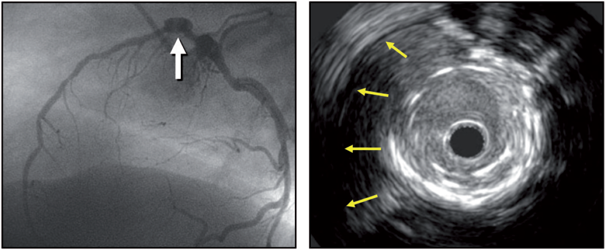
Figure 12
A coronary aneurysm is seen in the proximal segment of the left anterior descending by angiography and on IVUS, the yellow arrows show the separation of the vessel wall from the stent.
Research applications
Intravascular imaging has played an important role in the understanding of atherosclerosis disease in humans and in the translation of novel therapies to the clinical arena.
DRUG EFFECTS ON ATHEROSCLEROSIS
The initial observations about a positive continuous relationship between coronary heart disease risk and blood cholesterol levels led to the conduct of a number of IVUS-based studies to evaluate the effect of different lipid-lowering drugs on atheroma size. Table 3.
Table 3. IVUS imaging progression/regression clinical trials
| Statins trials | Primary Endpoint | Results |
|---|---|---|
| REVERSAL (R) atorvastatin 80 mg vs pravastatin 40 mg | Percent atheroma volume (PAV) | At 18 months (mos), atorvastatin reduced progression |
| ASTEROID (NR) rosuvastatin 40 mg | Change in PAV and the change in nominal atheroma volume in the 10-mm subsegment | At 24 mos, rosuvastatin induced significant regression |
| SATURN (R) atorvastatin 80 mg vs rosuvastatin 40 mg | PAV | At 24 mos, both drugs induced significant (& similar) regression |
| COSMOS (NR) rosuvastatin 2.5 mg titrated to 20 mg | Percent change of plaque volume | At 18 mos, rosuvastatin induced significant regression |
| IBIS-4 (NR) rosuvastatin 40 mg | PAV | At 13 mos, rosuvastatin induced significant regression |
| STABLE (R) rosuvastatin 40 mg vs 10 mg | Virtual Histology-defined percent compositional volume | At 12 mos, rosuvastatin reduced necrotic core and plaque volume |
| JAPAN-ACS (R) pitavastatin 4 mg or atorvastatin 20 mg | Mean percentage change in PV | At 8-12 mos, both drugs induced significant (& similar) regression |
| PCSK9 inhibitors trials | ||
| GLAGOV (R) evolocumab 420 mg vs placebo | PAV | At 18 mos, evolocumab induced significant regression |
| HUYGENS (R) evolocumab 420 mg vs placebo | PAV (secondary endpoint) | At 12 mos, evolocumab induced significant regression |
| PACMAN-AMI (R) alirocumab 150 mg vs placebo | PAV | At 12 mos, alirocumab induced significant regression |
| ODYSSEY-J-IVUS (R) alirocumab 75 mg vs placebo | Percent change in normalized total atheroma volume. | At 36 weeks, alirocumab did not reach statistical significance |
| Cholesterol ester transfer protein (CETP) inhibitors | ||
| ILLUSTRATE (R) torcetrapib and atorvastatin vs atorvastatin alone | PAV | At 24 mos, no effect of toracetrapib addition on PAV |
| Triglyceride-lowering agent | ||
| CHERRY (R) eicosapentaenoic acid (EPA) 1800 mg plus pitavastatin 4 mg vs pitavastatin 4 mg | Plaque volume and composition | At 6-8-mos, no difference in treatment effect between groups |
| HDL-C mimetics | ||
| CHI-SQUARE (R) placebo, 3 mg/kg, 6 mg/kg, or 12 mg/kg CER-001 | Nominal change in the total atheroma volume | At ~9 weeks, CER-001 infusions did not reduce plaque |
| CER-001 Atherosclerosis Regression Acute Coronary Syndrome (R) CER-001 3 mg/kg or placebo | PAV | At day 78, CER-001 did not promote regression |
| ApoA-I Milano (R) placebo or ETC-216 at 15 mg/kg or 45 mg/kg | PAV | At ~7 weeks, ApoA-I Milano/phospholipid complex (ETC-216) produced significant regression |
| Thiazolidinediones | ||
| PERISCOPE (R) glimepiride, 1 to 4 mg, or pioglitazone, 15 to 45 mg | PAV | At 18 mos, pioglitazone slower progression of plaques |
| APPROACH (R) rosiglitazone (4 mg/d) or glipizide (5 mg/d) | PAV | At 18 mos, rosiglitazone showed mild plaque regression, but it did not affect plaque size more than glipizide |
| Anti-hypertensive drugs | ||
| CAMELOT (R) amlodipine, 10 mg; enalapril, 20 mg; or placebo | PAV | At 24 mos, amlodipine showed a non significant trend toward less progression of plaque, while enalapril and placebo showed progression. |
| PERSPECTIVE (R) perindopril 8 mg or placebo | Mean plaque cross-sectional area | At 3 year, perindropil did not change plaque size |
| OLIVUS (R) 10 to 40 mg of olmesartan or control | PAV | At 14 mos, olmesartan decreased plaque size |
| R is randomized; NR is non randomized. | ||
Changes in plaque characteristics may be a more relevant endpoint to predict risk of vascular thrombosis than plaque progression or regression of mild to moderate disease, but imaging tools to evaluate plaque characteristics accurately were not available until recently. Other limitations of using conventional greyscale IVUS to assess the natural history of atherosclerosis should be enumerated:
- catheterisation, which is an invasive procedure, is required for serial imaging;
- only a segment of the coronary tree can be studied;
- plaque composition is not obtained;
- there is no direct evidence linking changes in coronary plaques to clinical events.
Selected IVUS studies showing stabilization and regression of atherosclerotic plaques are included in table 2.
Anti-lipid therapies
The efficacy of lowering LDL-C with inhibitors of hydroxymethylglutaryl coenzyme A reductase (statins) is unequivocal. However, the change in atheroma size by statins is not constant across all IVUS studies. There are many potential explanations for these discrepancies in IVUS studies such as drug properties, dose and duration of treatment. In early studies such as the GAIN study , atheroma volume was not reduced by atorvastatin despite the reduction in LDL-C (86 vs. 140 mg/dL) at 12 months. By contrast, the REVERSAL study 4 showed that LDL-C levels were further lowered by atorvastatin versus pravastatin (110 mg/dL vs. 79 mg/dL): this was associated with an increase of 2.7 percent of atheroma volume in pravastatin-treated patients and in a 0.4 percent reduction in atheroma volume in atorvastat intreated patients.
The ASTEROID study demonstrated for the first time that rosuvastatin at high dose had plaque regression capabilities. At 24 months, treatment with rosuvastatin 40 mg daily resulted in lowering of LDL-C to 60.8 mg/dL and elevation of high-density lipoproteincholesterol (HDL-C) by 14.7%. These lipid effects were associated with statistically significant, albeit small, reductions in percentage atheroma volume (0.79 %) and total atheroma volume (6.8 %). Similar results were found in the The IBIS 4 , 103 STEMI patients were imaged with IVUS and radiofrequency ultrasonography (IVUS-VH) of the two non-infarct-related epicardial coronary arteries (non-IRA) after successful primary PCI. Patients received rosuvastatin (40 mg/day) for 13 months and serial intracoronary imaging with the analysis of matched segments was available for 82 patients with 146 non-IRA. After 13 months, PAV of the non-IRA decreased by -0.9% (95% CI: -1.56 to -0.25, P = 0.007). Patients with regression in at least one non-IRA were more common (74%) than those without (26%). A unique highlight of the IBIS4 study is that its main findings were replicated by an artificial intelligence algorithm.
The head-to-head comparison of atorvastatin and rosuvastatin was reported in the SATURN trial. Although rosuvastatin lower more LDL-C, plaque regression extend was of similar magnitude in both study arms. When statins alone do not achieve recommended targets, ezetimibe has been used in combination. This combination has not proven to exert additional plaque regression effects in the primary endpoints of the HEAVEN, ZEUS, PRECISE-IVUS and EZETIMIBE-ACS trials.(122–125). Despite its value the amount of plaque regression achieved by aggressive statin therapy remains very low (<1%).
Proprotein convertase subtilisin kexin type 9 (PCSK9) inhibitors have been introduced as alternative lipid lowering drug in cases of statin intolerance or in combination with statin when the LDL-C goals are not achieved. The effect of evolocumab on progression of coronary disease in statin-treated patients has been explored in the The GLAGOV Randomized Clinical Trial . The primary endpoint, percent atheroma volume, increased 0.05% with placebo and decreased 0.95% with evolocumab (difference, -1.0% [95% CI, -1.8% to -0.64%]; P < .001). This mechanistic effect on plaque size in combination with its beneficial effects on clinical outcomes made this drug a valuable therapy in patients with CAD. Similarly, in the HUGYENS trial, evolocumab consistently showed reduction in plaque size. In the PACMAN-AMI trial, alirocumab showed plaque regression in non-infarct related arteries, while in the ODYSSEY-J-IVUS a reduced dose of alirocumab did not reach statistical significance vs placebo in terms of plaque regression.
IVUS studies have also demonstrated coronary plaque modification in HDL-treated patients. The infusion of synthetic HDL-C particles containing the variant apolipoprotein, apoA-I Milano, complexed with phospholipids (ETC- 216) reduced the percentage atheroma volume by -1.06% (3.17%; p =0.02 compared with baseline) in the combined ETC-216 group at 5 weeks. On the contrary, in the placebo group, percentage atheroma volume increased by 0.14% (3.09%; p =0.97 compared with baseline). In the ERASE study , 60 patients were randomly assigned to receive 4 weekly infusions of placebo (saline), 111 to receive 40 mg/kg of reconstituted HDL (CSL-111), and 12 to receive 80 mg/kg of CSL-111. The study was discontinued due to liver function test abnormalities. Within the treated group, the percentage change in atheroma volume was -3.4% with CSL-111 (p<0.001 vs. baseline), whilst for the placebo group it was -1.6% (p = 0.48 between groups). It remains unclear what the future holds for these therapeutic agents.
Patients with a deficiency of cholesterylester transfer protein (CETP) have elevated circulating levels of HDL-C. This has led to investigation on CETP inhibition as a novel and potentially effective approach to elevate HDL-C. In the ILLUSTRATE trial, the percentage atheroma volume (the primary efficacy measure) increase was similarly low in patients receiving atorvastatin monotherapy versus those receiving the combined torcetrapib–atorvastatin therapy after 24 months (0.19% vs. 0.12% respectively) .
Non lipid targets
Thiazolidinediones (TZDs) increase insulin sensitivity in peripheral tissues, thereby lowering glucose. In addition, TZDs (i.e., rosiglitazone and pioglitazone) lower blood pressure, reduce inflammatory markers, and improve lipid profile, endothelial function, and carotid IMT. TZDs may therefore reduce progression of coronary atherosclerosis compared to other antidiabetic drugs. Two studies have addressed this question, the APPROACH (Assessment on the Prevention of Progression by Rosiglitazone on Atherosclerosis in Type 2 Diabetes Patients with Cardiovascular History) trial, and the PERISCOPE (Comparison of Pioglitazone vs. Glimepiride on Progression of Coronary Atherosclerosis in Patients With Type 2 Diabetes) trial. Rosiglitazone significantly reduced normalised total atheroma volume (TAV) by 5.1 mm3 (95% CI -10.0, -0.3; p=0.04) when compared to glipizide, whereas pioglitazone just failed to achieve statistically significant change in total atheroma volume (–5.5±1.6 vs. –1.5±1.5 mm3, p=0.06) when compared to glimepiride. Change in PAV in the APPROACH study was no different in patients allocated to glipizide or to rosiglitazone (-0.64%, 95% CI -1.46, 0.17; p=0.12), while in the PERISCOPE study pioglitazone vs. glimepiride was associated with favourable effects on change of PAV (–0.16±0.21 vs. 0.73±0.20%, p=0.002). Pioglitazone resulted in plaque size reduction comparable to rosiglitazone but this reduction was associated with an almost double reduction in vessel size so that the change in normalised lumen volume was quite comparable. Change in percentage atheroma volume with, as numerator, change in atheroma volume and, as denominator, change in vessel volume may mask the specific directional changes in its numerator and denominator when used as primary endpoint to compare two pharmacological agents.
Anti-hypertensive drugs
Systolic blood pressure has been shown to be an independent predictor of plaque progression by IVUS. In the CAMELOT trial, amlodipine, enalapril and placebo were compared. Amlodipine showed, albeit non-significant, regression of plaque, while the other two groups showed progression. It showed that patients treated with amlodipine had a reduction in plaque size and also a reduction in cardiovascular events as compared to placebo at 24 months. The PERSPECTIVE study , a substudy of the EUROPA trial, evaluated the effect of perindopril on coronary plaque progression in 244 patients. There were no differences in changes detected in IVUS plaque measurements between the perindopril and placebo groups. Conversely, olmesartan decreased plaque size in the OLIVUS trial. Lastly, the AQUARIUS trial did not show beneficial effects with the use of aliskiren.
VASCULAR RESPONSE TO NON-METALLIC ENDOVASCULAR DEVICES
The feasibility and safety of a bioabsorbable everolimus-eluting vascular scaffold (BVS) was also assessed with intravascular imaging. In a prospective, openlabel study, 30 patients with a single de novo lesion that was suitable for treatment with a single BVS were enrolled. At 6-month follow-up, the angiographic in-stent late loss was 0.44 (0.35) mm and was mainly due to a reduction of the stent area (-11.8%) as measured by intravascular ultrasound. The neointimal area was small (0.30 [SD 0.44] mm2), with a minimal area obstruction of 5.5%. At 2 years, intravascular ultrasound showed a significant increase in minimal luminal area and average luminal area and volume, together with a significant decrease in plaque area and volume between 6 months and 2 years.
A third-generation coronary drug-eluting resorbable magnesium scaffold (DREAMS 3G) was developed to enhance the performance of previous scaffold generations and achieve angiographic and intravascular imaging outcomes comparable to those of contemporary drug-eluting stents.In the BIOMAG I study 116 patients (117 lesions) were enrolled. At six months, in-scaffold late lumen loss was 0.21 mm (SD 0.31). Intravascular ultrasound assessment showed preservation of the scaffold area (mean 7.59 mm2 [SD 2.21] post-procedure vs 6.96 mm2 [SD 2.48]) at six months) with a low mean neointimal area (0.02 mm2 [SD 0.10]).
High-definition IVUS
High-definition (HD) IVUS relies on the use of transducers with higher frequencies (55 to 70 MHz) that allow a superior spatial resolution (~40-60 microns vs ~150 microns). Table 1.
The technical challenge to develop high-frequency transducers is that the signal-line (micro-coaxial cable) that connects with the transducer may disturb the vibration of the piezoelectric layer at the site of transducer aperture. This phenomenon, potentially inducing reduced sensitivity, shortened penetration depth and distorted bean profile, becomes more serious as the center frequency of transducer increases. Some technical improvements, including dual-frequency technique and other advancements, allow the use of frequencies above 40-MHz for coronary applications in the clinical setting. Recent HD-IVUS systems also incorporate additional advances allowing a faster acquisition (pullback speed up to 10 mm/sec and 60 images/sec) and powerful signal processing to improve the signal/noise of the final images. Besides, they incorporate friendly touch panel interfaces and improved software to facilitate image interpretation and readily perform reliable measurements in the catheterization laboratory. HD-IVUS allows a more precise visualization of intraluminal structures and provides further insights on tissue characteristics at the vessel wall . In the coronary space the theoretical trade-off of a shallower tissue penetration does not appear to represent a significant problem in clinical practice. Likewise, although the intensity of the blood speckle increases with higher transducer frequencies this phenomenon rarely limits the identification of the lumen-tissue boundary.
The superior spatial resolution of HD-IVUS has generated major interest among interventional cardiologists and researches to better assess subtle morphological details on complicated plaques in ACS patients and also to better visualize the results of stent implantation. This is of interest because in the last years the unsurpassed spatial resolution of OCT has been a key factor to explain a displacement in the use of conventional (40 MHz) IVUS favoring OCT, particularly in Europa .
HD-IVUS and Culprit Plaques
The value of HD-IVUS to unravel the underlying pathological substrate of ACS patients has generated major clinical interest. Classical studies comparing 20-MHz IVUS and 40-MHz IVUS with OCT consistently emphasized the superiority of OCT to detect plaque rupture. Indeed, less than half of the plaque ruptures detected by OCT can be identified by conventional IVUS. In a recent study Ohashi et al prospectively compared HD-IVUS vs OCT to assess culprit lesions of 70 patients presenting with ACS. When required manual thrombectomy was employed to remove thrombus burden. Pre-intervention imaging, of good enough quality for adequate analysis could be obtained with HD-IVIS and OCT in 100% and 77% of cases, respectively. This suboptimal results with OCT were the result of incomplete blood removal or major shadowing of the arterial wall caused by significant residual thrombus. Plaque rupture was defined as a fibrous cap discontinuity with a communication between the lumen and the inner core of the plaque or a cavity within the plaque. HD-IVUS had a high sensitivity (85%) but a modest specificity (57%) to identify OCT-derived plaque rupture that was used as the gold standard . This study demonstrates the superiority of HD-IVUS for the detection of ruptured plaques as compared with conventional IVUS . Other studies have also confirmed that in some ACS patients OCT is unable to recognized plaque rupture due to the presence of residual fresh thrombus and that, in this setting, HD-IVUS is actually superior to OCT to identify the rupture site .
Preliminary studies also suggest that HD-IUS may provide some insights on mechanisms of ACS different from plaque rupture which, until very recently, were only recognized with OCT. Cuesta et al obtained HD-IVUS coronary images in 4 patients with ACS and a “definitive” diagnosis of plaque erosion by OCT. In these patients HD-IVUS images revealed minor laden thrombus, surface irregularities and a layered appearance of the underlying plaque, highly suggestive of this difficult diagnosis. In another combined HD-IVUS / OCT report, Antuña et al described features typical of intraplaque hemorrhage in a patient presenting with ACS and transient ST-segment elevation. The presence on HD-IVUS of a well-delineated echolucent “black” area, located relatively deep into the plaque, with an adjacent plaque showing a bright speckling pattern, could be identified in this patient in whom a diagnosis of intraplaque hemorrhage was subsequently confirmed by OCT . Finally, in some ACS patients presenting with spontaneous coronary artery dissection conventional IVUS may yield suboptimal images of the intimo-medial membrane, intracoronary thrombus and the intramural hematoma . In these patients HD-IVUS has been suggested to improve visualization of these structures close to the vessel surface . Although the diagnosis of plaque erosion, calcified nodule and intraplaque hemorrhage remains very challenging, available clinical data suggest the superiority of HD-IVUS over conventional IVUS in these elusive anatomic scenarios.
HD-IVUS and Coronary Interventions
A preliminary study with HD-IVUS and OCT image-coregistration suggested that HD-IVUS was superior to OCT evaluate the full vessel (due to its superior tissue penetration), particularly in the presence of lipid plaques that strongly attenuated the OCT signal. In this report side-love artifacts were more pronounced on HD-IVUS and OCT was also superior in delineating intraluminal structures. In a prospective study, García-Guimaraes et al compared the value of HD-IVUS and OCT, systematically performed before and after stent implantation, in 29 patients. Pre-intervention, HD-IVUS enabled a better visualization of the external elastic lamina (maximal arc) whereas OCT more frequently revealed the presence of plaque rupture or intraluminal thrombus. Of concern, some lipid-laden lesions by OCT were classified as fibrotic by HD-IVUS. Post-intervention OCT was superior to HD-IVUS to detect plaque protrusion, edge-dissections and number and percentage of malapposed struts. Notably, however, there were no differences (with an excellent agreement and intra-class correlation coefficient) between the 2 techniques in lumen and stent area measurements. Indeed, the systematic overestimation of lumen areas by conventional (40 MHz) IVUS as compared with OCT and phantoms in classical studies was not found in this study that demonstrated an excellent correlation between both imaging techniques in area measurements, likely as the result of the superior resolution currently obtained by HD-IVUS . On the other hand, the high resolution obtained by HD-IVUS has been also used to get further diagnostic insights in patients treated with stents that obtain suboptimal fractional flow reserve values (<0.85) immediately after the intervention . In these patients plaques at the stent edges, focal areas of stent underexpansion and strut malapposition are frequently disclosed with HD-IVIS .
Other studies suggested the value of HD-IVUS to optimize implantation of bioresorbable vascular scaffolds. Okada et al demonstrated that polymeric struts of bioresorbable vascular scaffolds were much better visualized by 60-MHz HD-IVUS than with conventional 40-MHz IVUS. Experiments were performed in vitro in a bench model and also in an in vivo swine coronary model, using OCT as the standard reference. Both conventional and high-speed HD-IVUS pullbacks were evaluated. Interestingly, OCT-derived lumen areas and strut abnormalities correlated significantly better with HD-IVUS than with conventional IVUS .
HD-IVUS has already become the standard technique for ultrasound-based imaging in most laboratories around the word. Further studies are still required to confirm the superiority of this technique over conventional IVUS and also its relative value over OCT in specific clinical and anatomic scenarios.
Personal perspective
Intravascular ultrasound was the first intravascular imaging technique developed to overcome the limitations of angiographic “luminography”. This technique has contributed enormously to our current knowledge of coronary artery disease through its capacity to obtain in vivo images of the coronary vessel wall structure and atheromatous plaques in most diverse coronary syndromes. In addition, IVUS has played an important role in the field of PCI, contributing to our understanding of the pitfalls of stent deployment and improving stent techniques, resulting in a decrease in the number of periprocedural complications and which has led to the formulation of the antithrombotic treatments used today. The analysis of the radiofrequency data has ushered in a new era. In the PROSPECT study, tissue characterisation of plaques had a predominant role and a positive association was found between specific tissue types and clinical events. Although these observations do not warrant any change in our current clinical practice, they urge us to investigate whether local or systemic treatments would have an effect on the number of clinical events. At present, integration of multiple image technologies in a single catheter provides a more comprehensive assessment of the coronary vasculature. The combined use of IVUS-VH analysis and OCT seems to improve the accuracy for TCFA detection. Another combination is NIR spectroscopy and OCT. Both imaging techniques are light-based which may facilitate their combination in one single catheter. Using NIRS, an accurate characterisation of necrotic core can be achieved, while OCT will provide morphological information about the relationship of the necrotic core and lumen, as well as information on the fibrous cap overlying the pool of necrotic core. A real breakthrough is the hybrid IVUS/OCT catheters, although there are many in the pipeline, the Novasight Hybrid System (Conavi, Toronto, Ontario,Canada - http://conavi.com/novasighthybrid/) has already received approval from FDA and from Ministry of Health, Labor and Welfare (MHLW) in Japan. The clinical application will be more clearly defined once the first clinical studies are reported. IVUS guidance during some interventional procedures may increase the likelihood of a greater success rate, specifically in the context of the treatment of chronic total occlusions, in which the most challenging part of the procedure is to cross the proximal part of the occlusion and to keep the guidewire within the limits of the vessel structure to avoid coronary perforations.