Masahisa Yamane, Kenya Nasu, Masaaki Okutsu, Makoto Sekiguchi
Chronic total occlusion
Updated on August 26, 2021
Chronically occluded coronary lesions make up about 20% of all coronary lesions, but because a lesion is totally occluded it is often considered differently from a non-occlusive lesion regarding the indication of an intervention. There are numerous studies including a recent randomized trial to support the rationale of reopening a chronic total coronary occlusion (CTO) if viability and ischaemia are demonstrated in the territory distal to the CTO. The reluctance of many operators to attempt a CTO as a target lesion is rather based on the complexity of the procedure, and the limited success rate than on any evidence that a CTO is a benign lesion. However, recent developments in the technical approach, both in strategy as well as available tools, have led to a greatly improved success rate for the recanalization of a CTO which is now above 90% in experienced hands. Furthermore, persistent patency and low lesion recurrence can be achieved through the use of drug-eluting stents (DES). To achieve these improvements in technical success, operators need to undertake specialised training, and must become familiar with the specific tools and techniques of CTO intervention.
A chronic total occlusion (CTO) describes a completely occluded coronary artery. A variety of definitions existed regarding the TIMI (Thrombolysis in Myocardial Infarction) flow and the duration of the occlusion. This influences the comparison of data on acute and long-term outcomes, and the advice given regarding which technical approach to undertake for crossing a lesion successfully , .
In order to find common ground for future discussions of technique and patient outcome, a consensus was reached by a group of European experts suggesting a firm definition of CTOs as those occluded arteries with an angiographic documented or clinically suspected duration of occlusion of at least 3 months with absolutely no flow through the lesion (TIMI 0 flow) . Bridging collaterals may make it difficult to discriminate between a total and a subtotal occlusion, therefore careful angiographic analysis in multiple planes is required. Occlusions of 1 to 3 months duration can be addressed as recent occlusions, and within 4 weeks after an acute myocardial infarction, as subacute occlusions.
The basic pathological feature of a CTO consists firstly of a proximal cap, which is often fibrotic or calcified and may provide considerable resistance to wire advancement. Then along the occlusion length there follows a segment of loose fibrous tissue or organised thrombus with various degrees of adventitial and intraluminal neovascularisation, and variable extent of calcification , . The presence of so called microchannels which might facilitate wire passage during intervention was based on these older pathological studies, which included a number of subtotal CTOs not fulfilling the modern-day definition. A recent pathological study in a large group of CTOs, however, observed traversing microchannels infrequently . Sometimes, neovascularisation may establish antegrade flow through the lesion, and change the CTO to a functional occlusion. If this segment is very long, as most often occurs within the right coronary artery (RCA), multislice computed tomography (MSCT) might be helpful in defining the general direction of the vessel course and the extent of calcification, and also in defining whether such calcification is limited to the vessel wall or represents a calcified central plaque occlusion , . Finally, the distal cap needs to be passed towards the segment distal to the occlusion which is often tapered and constricted and provides a small target for the distal wire entry (Figure 1).
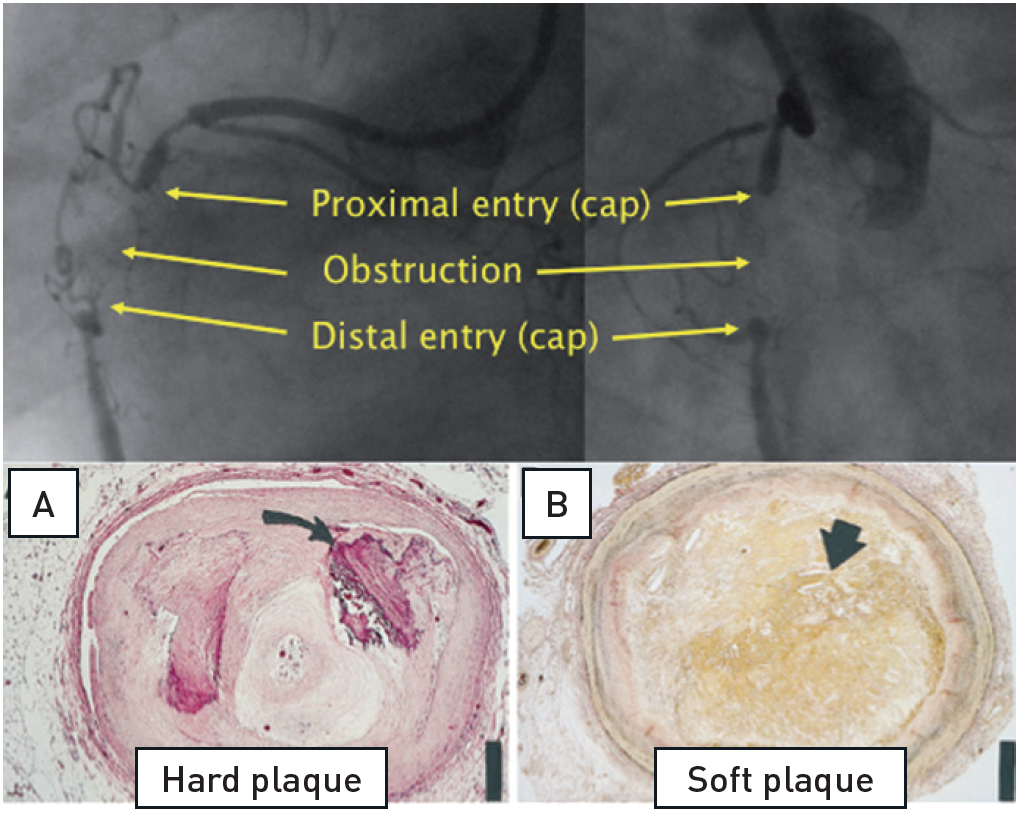
The basic features of a CTO of the RCA with the proximal and distal cap, and a variable length of occlusion in-between. Histological cross sections of various morphological compositions (adapted from).
A. Hematoxylin-eosin stain) of a representative hard or fibrocalcific chronic total occlusion (CTO) with extensive calcification (arrow). B, Low power view (elastic van Gieson stain) of a representative soft or lipid-laden CTO intimal plaque with extensive cholesterol deposition (arrow).
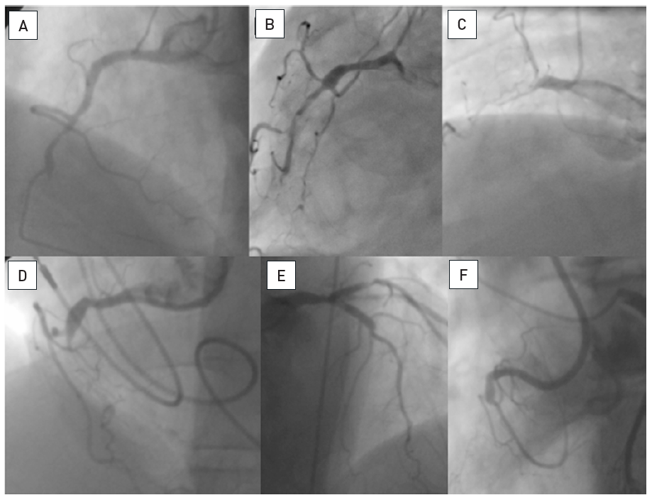
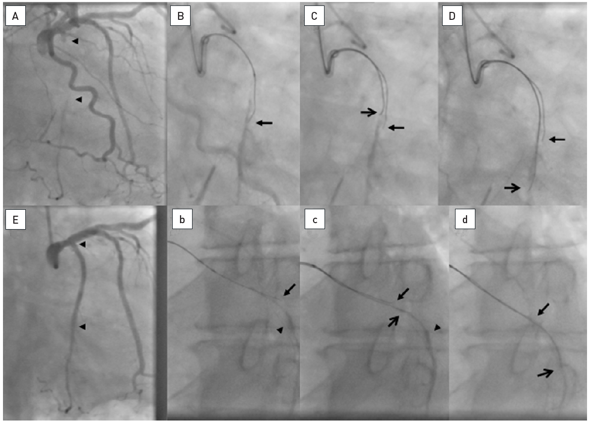
The data on the prevalence of CTOs in patients with coronary artery disease varied from 20% to 30% , , but contemporary large registries of consecutive patients from Canada and Sweden point to a prevalence of 15-18%. Still, in contemporary clinical practice the number of CTOs makes up only 6% to 10% of PCI volume , , , . In a nation-wide survey of the US even only 3.8% of PCI procedures were conducted in CTOs . CTO represent a unique set of lesions not only because of the complexity of the required interventional technique, but also with regards to the discordant view on the clinical indication to treat these lesions. Historically the presence of a CTO meant medical therapy or referral for CABG. In general, patients with a CTO present with stable angina pectoris except if other coronary lesions progress and lead to unstable angina. Concurrent CTOs pose a high risk if the collateral supplying artery is involved in an acute myocardial infarction, as the territory at risk is increased , (Figure 2).
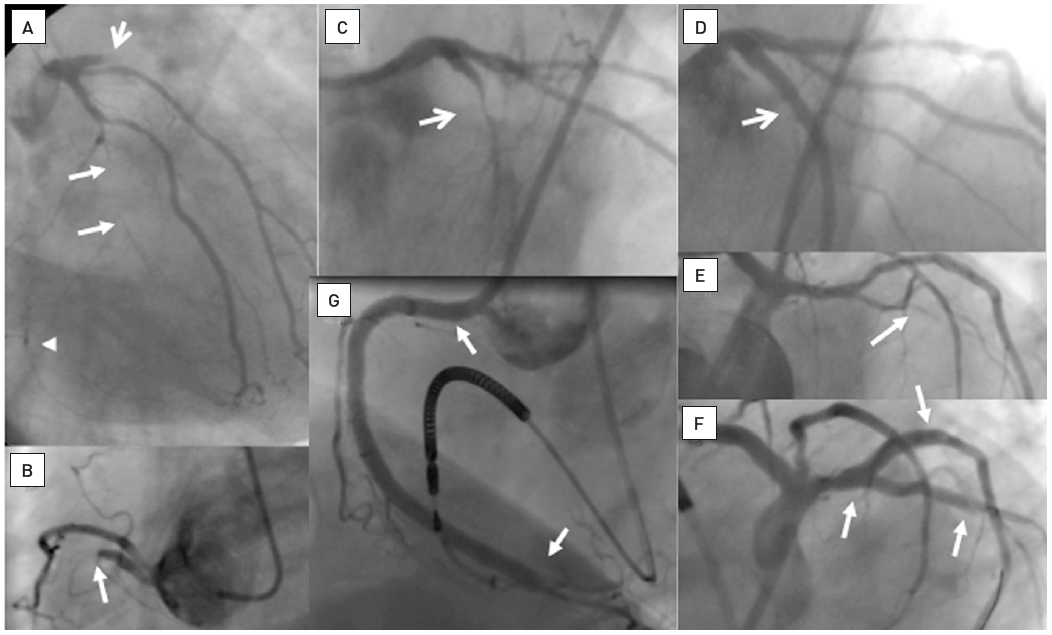
A 54 year old male without previous history of coronary artery disease admitted for acute chest pain with anterior ST elevation. He has an acute proximal LAD occlusion (open arrow; A) as well as chronic occlusions of the mid LCX with ipsilateral collaterals (between arrows), and a proximal RCA (arrow, B), supplied via collaterals from the LCX (arrow head, A). Primary PCI of the LAD is performed with thrombus aspiration (open arrow, C) with DES (between open arrows, D). Before the next stage an ICD was implanted, and then the LCX was recanalised (arrow, E) with bifurcation stenting (between arrows, F). In a third stage, the RCA is recanalised with four DES (G).
There are four main reasons to indicate whether a recanalization attempt should be made in a patient with a CTO:
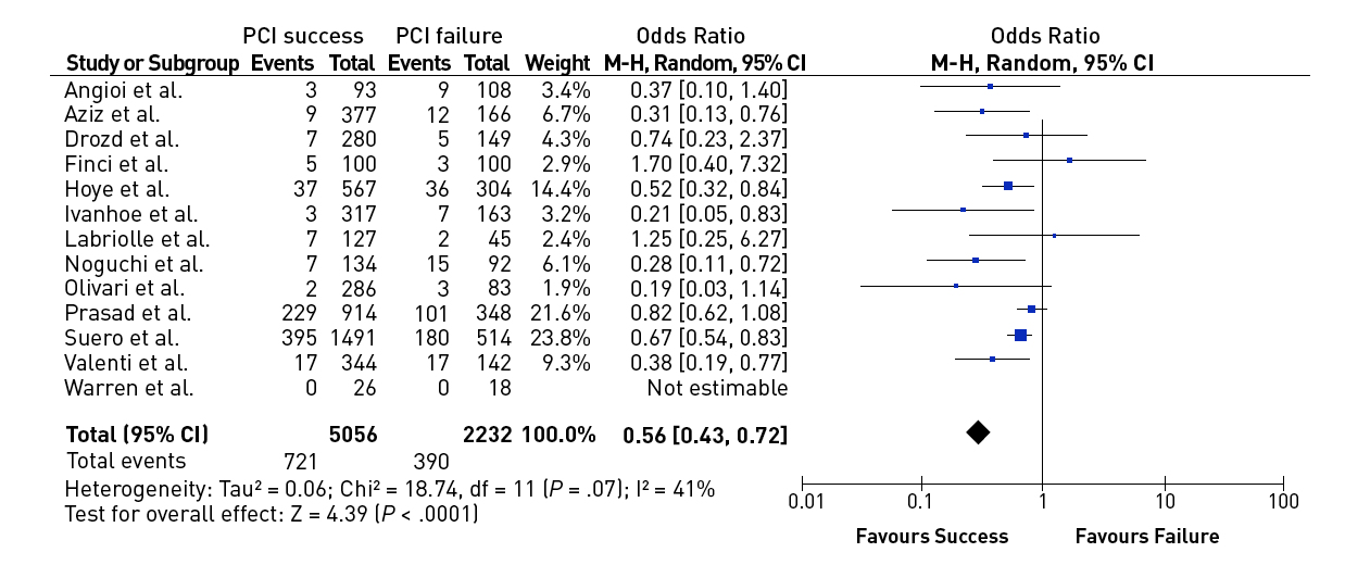
In a meta-analysis of trials comparing successful and unsuccessful procedures the impact on clinical symptoms of angina was analysed . In six trials in which recurrence of angina was reported, this event occurred about 50% more often after an unsuccessful as compared to a successful procedure , , , , , (Figure 3). This meta-analysis compared 1,030 successful with 570 unsuccessful procedures, the success rate in these studies was well below 70% as the studies originated from a period before advanced recanalization techniques had been introduced. Lesion recurrence, leading to a recurrence of symptoms, was a frequent observation in the era of balloon angioplasty and bare metal stent (BMS) treatment of CTOs , , .
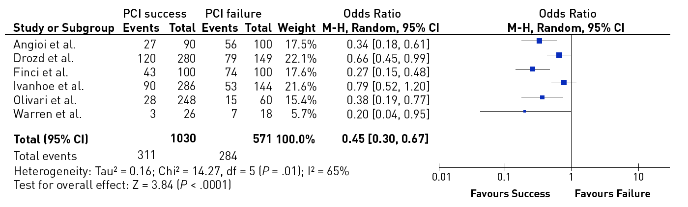
Effect of successful versus failed PCI for a CTO on the presence or absence of residual angina during follow-up (from).
The problem with symptoms related to a CTO is their often atypical presentation. Unlike patients with non-occluded lesions, there is a baseline collateral blood supply to the myocardial territory distal to the occlusion which is fully developed after about 3 months of occlusion duration . The chronic nature of the situation may lead patients to adapt to their limited exercise capacity and not report this limitation as an acute symptom. More often the patient will experience dyspnoea at higher exercise levels rather than typical angina. The phenomenon of a walk-through angina, i.e. relieve of initial symptoms with continued exercise, although typical for CTO related-symptoms, may not always lead the patient and the physician to the right conclusion of the underling disease.
The effect of a successful revascularisation was recently evaluated by the Seattle Angina Questionnaire (SAQ) to assess quality of life (QoL) in the FACTOR trial . The authors observed an improvement in QoL after successful PCI, which was most pronounced in patients with a symptomatic state before PCI, whereas the improvement was less evident in asymptomatic patients. In a comparison of clinical symptoms at baseline and after successful treatment between patients with and without a CTO as target lesion, the physical limitation assessed by the SAQ was more severe, but the improvement after treatment more pronounced in CTO patients .
Many of the patients with a CTO will be considered patients with silent ischaemia. Despite the observation that collaterals will prevent regional dysfunction and MI in many of these patients, the functional capacity of the collateral system to increase myocardial blood supply during exercise is limited , . The fractional flow reserve (FFR) assessed distal to an occluded artery is typically in the range below 0.5 , which clearly indicates myocardial ischaemia , . As there is a considerable amount of data supporting the revascularisation of coronary lesions causing silent ischaemia of more than 10% of myocardial volume , , , as reflected in the recent ESC-EACTS guidelines on myocardial revascularisation , this applies also to CTOs with a similar evidence of myocardial ischaemia. Based on the aforementioned subjective adaptation to clinical symptoms, the performance of quantitative ischaemia tests should be encouraged in asymptomatic patients with CTOs.
The potential effect of a reopened CTO on LV function was established with the first attempts to treat CTOs by PCI, but no randomised trial has been performed, and the only data are derived from comparing failed and successful PCI attempts. When reviewing these early studies, one needs to bear in mind that they were done with balloon angioplasty alone, or with BMS later on, but not with DES. Lesion recurrence as a major detrimental factor for the functional improvement was very high in those studies . The effect of global LV function as assessed by ejection fraction (EF) is generally less pronounced than the effect on regional function. The improvement of LV EF varied, but vessel patency was mandatory for the achievement of LV recovery , , , , , . Other predictors of LV improvement were a shorter duration of occlusion (<6 months), and a more severely impaired LV function at baseline (<60%) .
In the case of ischaemia related regional impairment as assessed by dobutamine stress echocardiography, functional recovery may take place immediately after a successful PCI . LV recovery starts within 1 to 4 weeks after revascularisation and is usually complete within 3 months , , . Although these studies were done after surgical revascularisation, they are probably applicable also to PCI. Most studies cited above evaluated LV recovery after PCI at a follow-up of 6 to 12 months but may take longer in some cases .
Recovery of LV function in chronically ischaemic myocardium depends on the presence of hibernating or stunned but viable myocardium , . Magnetic resonance imaging (MRI) is now the gold standard to detect irreversibly damaged myocardial scar tissue and helps to highlight where revascularisation (surgical and interventional) is indicated. When MRI is applied to patients with a CTO, the transmural extent of late enhancement and also the residual wall thickness of viable myocardium are related to the improvement of LV function after PCI , . The extent of transmural late enhancement is a readily available measure, however, a linear relationship with LV recovery is difficult to establish as, among other factors, the spatial extent needs to be considered as well. So, at present, definite LV function improvement is predicted with a cut-off value of late enhancement of <25% wall thickness, with a large grey zone with uncertainty of recovery of 25% to 75% wall thickness. Some further improvement can be expected in this "grey" zone between 6 months and 3 years after PCI, but these improvements are moderate . The additional use of low dose dobutamine stress during the MRI examination protocol may improve the prediction of wall motion recovery and improve the indication for revascularisation . No recovery is expected with complete transmural extent of scar tissue (Figure 5).
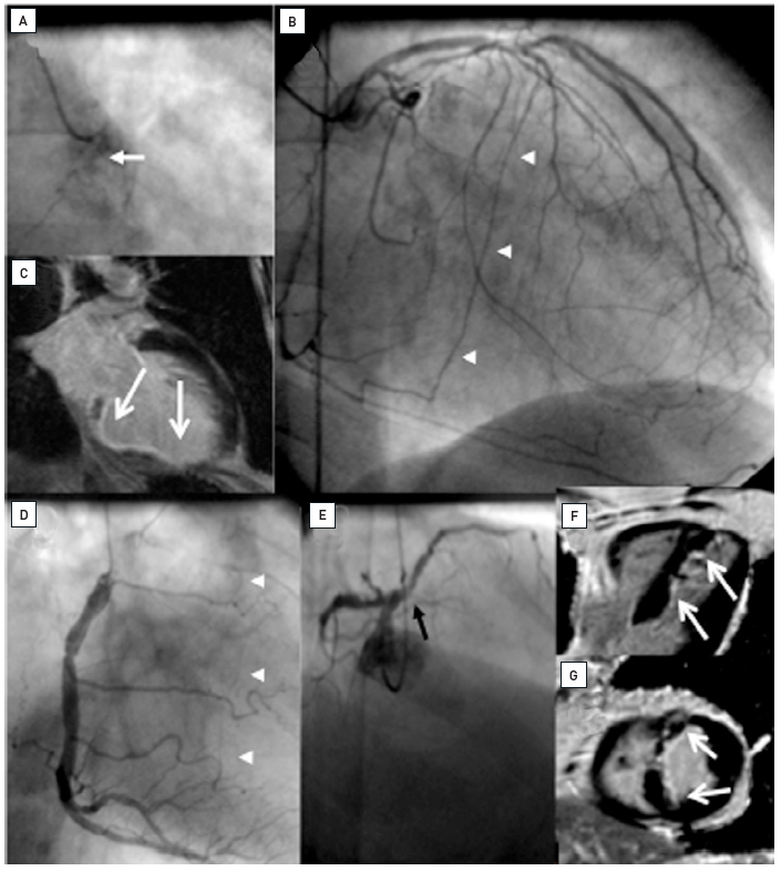
Two examples of CTOs with collateralisation, but different viability. A: Proximal RCA occlusion (arrow) supplied by well-developed CC2 collaterals (arrow heads) from the LAD (B). However, MRI shows complete transmural late enhancement (arrows, C): no indication for recanalization. E: Ostial LAD occlusion (arrow) with CC1 collaterals from the RCA (arrow heads, D). Despite this less extensive collateralisation, MRI shows only subintimal late enhancement in two views (E, F: arrows): this CTO was successfully recanalised.
In patients with stable angina pectoris, no single large randomised clinical trial on revascularisation versus medical therapy has so far shown an improvement in survival. Still the debate is open as to whether individual trials had enough power to detect a prognostic difference . One of many meta-analyses concluded that there is indication of a survival benefit when treating patients with stable angina by PCI , but this opinion is not uniformly supported and needs further corroboration from a future larger scale randomised trial . Recent epidemiologic data from Sweden’s SCAAR registry support the fact that the presence of a CTO is associated with increased cardiac mortality.
If we look at a very large registry of CTO PCI from UK including more than 13000 patients , a mortality benefit in patients with a successful PCI as compared to failed procedures was demonstrated, but the absolute values after 3 years were just 5 vs 7% and the significance of the difference was derived from the large number of patients. If such a benefit would be addressed in a randomized trial, one should keep in mind that randomized trials tend to include less symptomatic patients, and the likelihood of showing a difference in survival in a low-risk selection of patients will be low. The one-year mortality in the UK registry was between 2 and 3%, whereas in a recent randomized trial the one year mortality of enrolled patients in the PCI arm was just 0.8% , underscoring the selection bias in the inclusion process of randomization.
Because CTOs had a low likelihood of interventional success they were not well represented in trials on stable angina. That the risk of leaving a CTO alone is not negligible is highlighted by the observation of the severe prognostic impact on outcome if an acute MI occurs in the presence of a CTO in one of the other arteries. The 30-day mortality is tripled despite the STEMI treatment by primary PCI , and the incidence of cardiogenic shock increases . The further long-term prognosis of the initial survivors is adversely influenced through a follow-up of 5 years (Figure 6). The negative prognostic impact in patients experiencing a STEMI was also confirmed by post-hoc analysis from randomized trials of STEMI PCI such as the HORIZONS and TAPAS trials, . The randomized EXPLORE trial was designed to assess the potential impact of a CTO PCI within 7 days after a STEMI as compared to OMT looking at changes of LV function as a primary endpoint, and clinical secondary endpoints. In 304 randomized patients, however, no positive influence of CTO PCI was observed after 4 months, and no clinical difference. The problem of this trial was the long inclusion period of 8 years for a low number of patients, a low success rate of 73%, and the selection bias that will have excluded the most impaired patients.
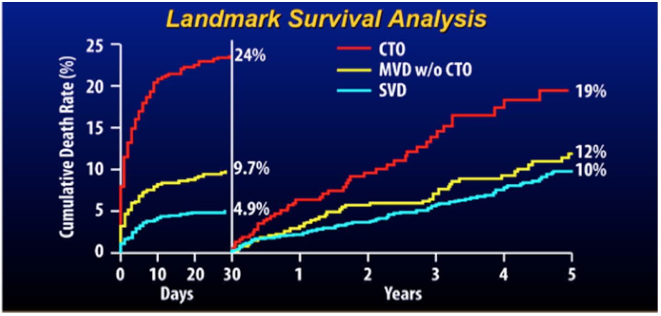
Cumulative risk of death during the first 30 days after primary percutaneous coronary intervention (PCI) and thereafter for patients with single vessel disease (SVD), multivessel disease without a chronic total occlusion (CTO) (MVD), and multivessel disease including a CTO (from).
A number of registries reported on the long-term outcome of patients undergoing PCI for CTOs. However, all these data are comparisons between failed and successful procedures, and not randomised. Despite this crucial shortcoming, the uniform impression is that successful recanalization has a positive effect on survival (Figure 7). However, one should be cautious in extrapolating these registry observations as there are limitations in selection bias, and above all they represent data mainly from a historical perspective that is no longer comparable to today’s standard of treatment , , , , , , , , , , , , . One uniform observation in many of these studies was the reduced need for CABG among patients with successful PCI for CTOs (Figure 8).
Effect of successful versus failed PCI for a CTO on all-cause mortality during follow-up [from ]
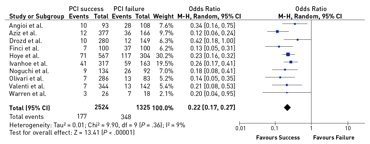
Effect of successful versus failed PCI for a CTO on the need for subsequent CABG during follow-up [from ].
A recent large registry from Japan extended to the era of DES and modern recanalization techniques . They compared patients with persistent patent arteries at follow-up with those with initial or late failure of patency and observed a significant difference in the survival rate of 92% versus 64% after 6 years. This registry stands out from the other data as it takes early failure and late reocclusion together and basically presents the comparison of long-term patent and re/occluded CTOs. Persistent patency might be an important additional factor for prognostic benefit, which is clearly better nowadays with DES than it had been in the era of balloon angioplasty and BMS. Several registries and one randomised trial have confirmed finally that CTOs should receive DES due to the higher recurrence rate after BMS .
The important negative impact of incomplete revascularisation on prognosis was reemphasised by the analysis of the SYNTAX trial. A high residual SYNTAX score (rSs) is related to increased mortality. The SYNTAX score is heavily influenced by the presence of a CTO, and therefore the presence of a CTO was the best predictor of incomplete revascularisation. CTOs are found in half of the patients with the highest rSs, which is explained by the low revascularisation success for CTOs within the SYNTAX trial PCI arm of less than 50% , . The relevance of CTOs as a major determinant of incomplete revascularisation is further supported by the application of the rSs on other studies like the ACUITY trial in a post-hoc analysis . In the recent SYNTAX II study modern function and imaging-based PCI technique were applied and a considerably higher success rate in CTOs of 87% as compared to the 50% success rate in the original SYNTAX PCI arm was achieved, leading to a considerably better outcome when compared to the historic PCI and CABG arm of the SYNTAX study. This underscores the relevance of treating multivessel patients with adequate PCI technique including the revascularization of any CTO in these patients in order to achieve an outcome comparable to CABG.
In 2017 two randomized trials of CTO PCI versus optimal medical therapy (OMT) had been presented in patients with stable angina, but only one of them is fully published. The DECISION-CTO study was presented at the American College of Cardiology Annual conference 2017. This trial in 834 patients with stable angina including a CTO as one of their lesions, showed no difference between PCI and OMT regarding the primary endpoint of death, MI, stroke or revascularization. In addition, both groups showed a similar improvement of SAQ subscales after randomisation and treatment. However, the trial design was compromised by the fact, that non-CTO lesions were treated after the baseline assessment. As 77% of patients having multi-vessel disease in DECISION-CTO, this meant, that about 70% of patients in the OMT arm of DECISION-CTO received PCI, which explains an improved SAQ even in the OMT group. The trial took more than six years to enrol, but presented a very high success rate of 90% for the CTO lesion. The other trial is the EUROCTO trial, presented at EuroPCR 2017, and now available in print has a similar patient population, but the main difference was, that all of the 448 enrolled patients were treated for the hemodynamically relevant non_CTO lesion before randomization and baseline assessment. Therefore, all confounding effects of the non-CTO treatment were eliminated. This trial showed with a high procedural success rate and a low cross-over rate from OMT of 7% in the intention-to-treat analysis, that the SAQ subscales of angina frequency and quality of life were significantly reduced in the PCI group as compared to the OMT group. This manifested that a positive endpoint was reached with a statistical power of 81%. In addition physical limitation was considerably reduced, as well as the CCS class at follow-up at no significant extra risk during the clinical follow-up (Figure 4). Both studies are in fact not contradictory, as the EUROCTO trial assessed the isolated benefit of CTO PCI, whereas DECISION-CTO tested the additional benefit of CTO PCI in addition to non-CTO PCI. The latter could not address in proper numbers the isolated effect of CTO PCI but showed that at least the combined non-CTO and CTO PCI did not lead to increased events during a three-year follow-up .
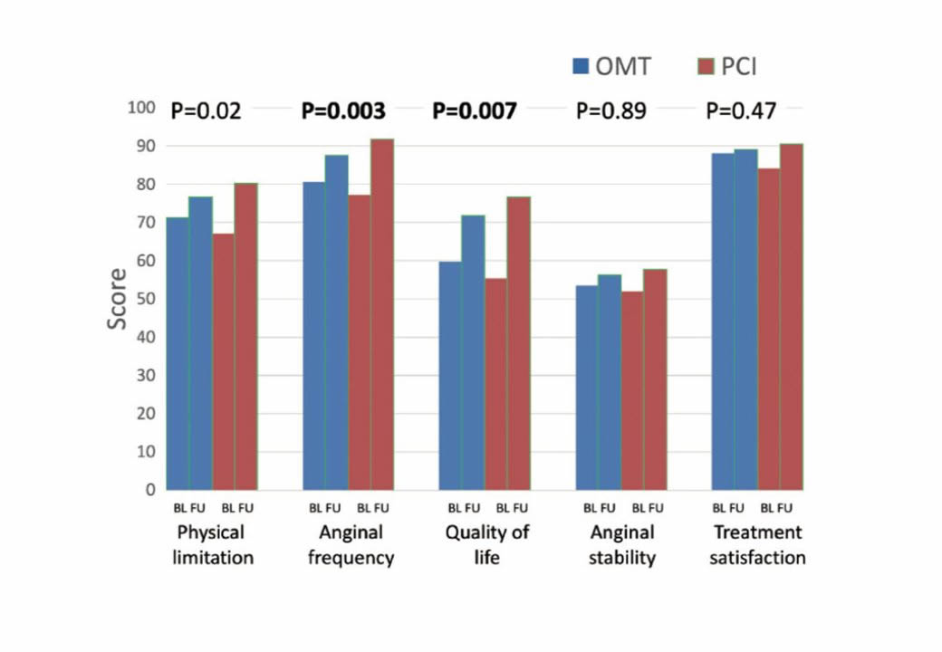
The primary outcome results from the EUROCTO trial: Seattle angina questionnaire subscale improve more 12 months after percutaneous revascularization as compared to optimal medical therapy alone in patients with stable angina pectoris and a CTO. (from).
A smaller trial addressed the question of recovery of left ventricular function in 205 patients randomized either to OMT or CTO PCI . This REVASC trial found no change of LV function parameters assessed by MRI in both treatment groups, but less MACE after CTO PCI. However, in this trial the proof of viability was not an entry criteria, and the baseline ejection fraction with 55-60% was rather high which makes it difficult to show an improvement after revascularization.
In an effort to stratify and standardize future research and clinical studies in the field of CTO PCI an Academic Research Conosrtium set up a series of definitions of anatomical features, procedural approach and technical details, as well as measures of outcome for CTO interventions .
Collaterals are inter-arterial connections that provide blood flow to a vascular territory whose original supply vessel is obstructed. Thus, the integrity of the organ supplied by the obstructed vessel may be preserved or to a certain degree impaired but would not become necrotic. In the coronary vascular system such connections are familiar to every investigator who performs angiographic imaging of patients with coronary artery disease. They develop through arteriogenesis, that is, through the recruitment of preformed and pre-existing inter-arterial connections mainly driven by shear forces along the pressure gradient that develops when the native vessel is occluded . Some of these connections may be preformed to such an extent that they are immediately recruitable during vessel occlusion, as shown during balloon occlusion in non-diseased coronary arteries . The functional assessment of collaterals, as mentioned below, has revealed that in patients without well-developed pre-existing collateral connections, collaterals required between 2 to 12 weeks to fully develop their functional capacity .
The size of the inter-arterial connections varies over a wide range from between 40 and 200 μm. However, the size of the majority of these vessels is below the spatial resolution even of analogue angiographic imaging. With today’s digital storage media and a resolution of >0.2mm, quantitative coronary angiography of collaterals, which would be ideal, is limited. The most widely used angiographic grading system described by Rentrop et al does not actually rate the collaterals themselves, but their effect in filling the occluded arterial segment . It distinguishes four degrees of collateral recipient artery filling by radiographic contrast medium: grade 0=no collaterals; grade 1=side branch filling of the recipient artery without filling of the main epicardial artery; grade 2=partial filling of the main epicardial recipient artery; grade 3=complete filling of the main epicardial recipient artery. Further refinements of qualitative angiographic methods consider other aspects of coronary collateral angiographic appearance, such as collateral flow grade, frame count, bifurcation count, collateral length grade, the relationship between the area at risk for myocardial infarction and collaterals, and collateral recipient vessel filling.
The Rentrop classification of angiographic collateral assessment was developed in the context of acute myocardial infarction and the time frame of first appearance of collaterals after an acute occlusion. However, in CTOs, the majority of collaterals provide Rentrop 3 filling. A different angiographic description of collaterals, which is also related to physiological function, is based on the visual estimation of the collateral diameter, the collateral connection grade according to Werner et al . This has gained relevance for the assessment of collateral pathways as possible interventional routes in the so-called retrograde approach (see below).
The physiological assessment of collateral function is best done with combined pressure and flow velocity recordings with microsensors . This provides a complete picture of the haemodynamics of the collateralised territory distal to an obstruction with the serial arrangements of 3 major conductance pathways relevant for collateral perfusion, that is (1) the conductance through the collateral proper, which is determined by the length and diameter of these collaterals, which may often show a tortuous vessel course, (2) the conductance in the segment of the collateral donor artery, where diffuse atherosclerosis may impede flow to the collaterals, and (3) the conductance of the arteriolar ramifications of the microcirculation of the myocardium distal to the occlusion , .
The phenomenon when collateral supply regresses during exercise is described as coronary steal. One of the major factors involved in coronary steal is the presence of a significant lesion in the collateral donor artery . The fact that a larger myocardial area is subtended by a donor artery segment when it feeds the main collateral supply may lead to a low FFR value of the donor artery lesion. Once the CTO is revascularized, the same lesion might show a higher FFR value as the myocardial mass distal to the lesion is then reduced. Therefore, physiologically driven revascularization in a donor segment needs to take this observation into account specifically when the values are near the cut-off value, .
Collateral function can develop to a similar functional level in patients post myocardial infarction with large akinetic territories as in patients with normal preserved regional function. The presence of viability is not a prerequisite for collateral development. This is in accordance with experimental studies on arteriogenesis, namely that the pressure drop along preformed inter-arterial connections is the driving force to recruit these connections in the presence of occlusion of the native artery (Figure 5).
It is known that collaterals have the capacity to prevent myocardial necrosis and may even uphold metabolic supply to the territory distal to an occlusion to maintain full contractile capacity. But direct assessment of collateral function shows that the functional competence of collaterals in CTOs is limited even in patients without a prior Q-wave MI. During a standard stress protocol with systemic infusion of adenosine the coronary flow velocity and pressure changes distal to an occlusion were well below cut-off values for assessing the functional reserve in non-occlusive coronary obstructions, that is a flow velocity reserve above 2, and an FFR above 0.75. So even well-developed collaterals would not prevent ischaemia during exercise , (Figure 9).
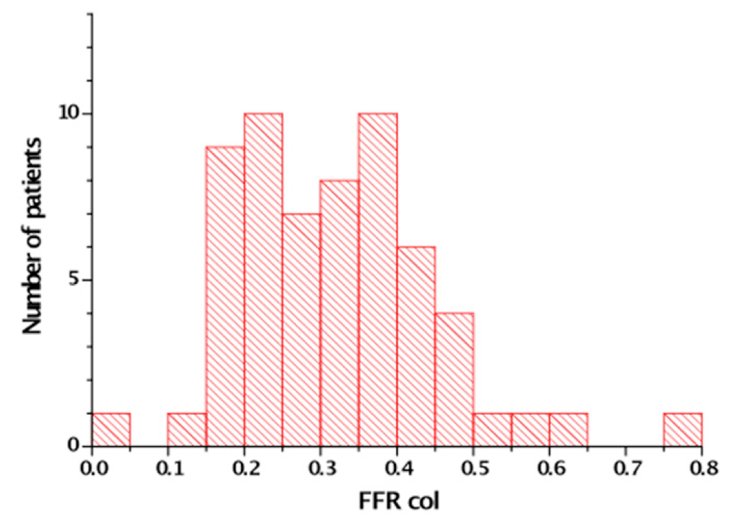
The fractional flow reserve (FFR) measured distal to a CTO after passage of a microcatheter. Maximum hyperaemia is induced by systemic infusion of adenosine (140 μg/kg/min). In 60 patients only one patient showed a FFR that was above the threshold of 0.75 [from ]
Collaterals will regress once the native artery that was supplied by the collaterals is revascularized. This process starts immediately after the re-established antegrade flow with immediate loss of collateral conductance and extends further many months after the angioplasty or revascularisation procedure. Acute reocclusion for example in the course of a late stent thrombosis would therefore lead to an acute coronary syndrome in most cases , , as the recruitment of collaterals is not instantaneous in most patients .
The ESC-EACTS guidelines on myocardial revascularisation clearly state that a CTO, like any other coronary lesion, requires revascularisation if it causes symptoms or ischaemia . There is a considerable amount of data supporting the revascularisation of coronary lesions causing silent ischaemia of more than 10% of myocardial volume , , , this applies also to CTOs with a similar evidence of myocardial ischaemia. Based on the aforementioned chronicity of and adaptation of clinical symptoms, the performance of quantitative ischaemia tests should be encouraged in asymptomatic patients with CTOs. Which mode of revascularisation - surgery or PCI, is not clearly defined and should depend also on factors such as the presence of multivessel disease, involvement of the left main coronary artery, impairment of LV function as well as the general prognosis and comorbidity of a patient.
The fact that CTOs are specifically addressed as a subset of coronary lesion with additional rating is historically based on the fact of previously very low success rates of CTO PCI. There is no clinical evidence that would justify to consider a CTO a less severe lesion than a high-grade stenosis. The success rate of a proposed PCI for a CTO must therefore be taken into consideration as compared to alternative modes. A recent decision algorithm for indicating CTO PCI is based on the presence of symptoms and viability, which is basically the same reasoning that governs PCI indication in general (Figure 10).
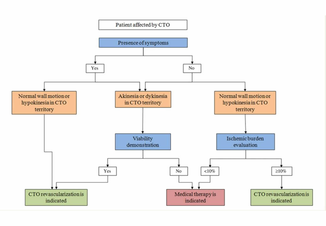
Indications of CTO revascularization according to symptoms, ischaemia, and viability. CTO, chronic total occlusion. (from).
The above mentioned criteria of ischemic burden as an indicator for revascularization even in asymptomatic patients was explored by the ISCHEMIA trial . There is no information on the number of CTO available, but given the known prevalence it should be in the range of 10-15%. The study overall indicated that there was no prognostic benefit in seeking an early invasive assessment and then revascularisation in these patients with stable angina. The study had included about one third of patients with no symptoms, however, in patients with more extensive symptoms, it could be shown that revascularisation provided a significant symptomatic benefit and improvement in quality of life . These results support the above-mentioned concept of considering CTO PCI a symptomatic treatment which will improve symptom control and quality of life. Whether asymptomatic patients with extensive ischemia would benefit from revascularisation has been challenged by the ISCHEMIA trial, but the selection bias in this trial lead to a rather low risk population, and similar to the results of COURAGE the transferability to the general population and the individual patient’s problem needs to be critically considered.
That a CTO requires specific techniques was recognised early by the pioneers of CTO recanalization such as Geoffrey Hartzler and Bernhard Meier . The procedural success rate of PCI in CTOs was initially in the range of 50%, that is why early guidelines for PCI even stated that the presence of a CTO was a contraindication for PCI , . However, this has changed considerably over the past two decades due to the technical developments described below , (Figure 11). The success rates in the hands of dedicated expert operators can reach a level of more than 90%, and the ESC-EACTS guidelines on myocardial revascularisation suggest a minimum level of 80% success rate for those who perform PCI in CTOs .
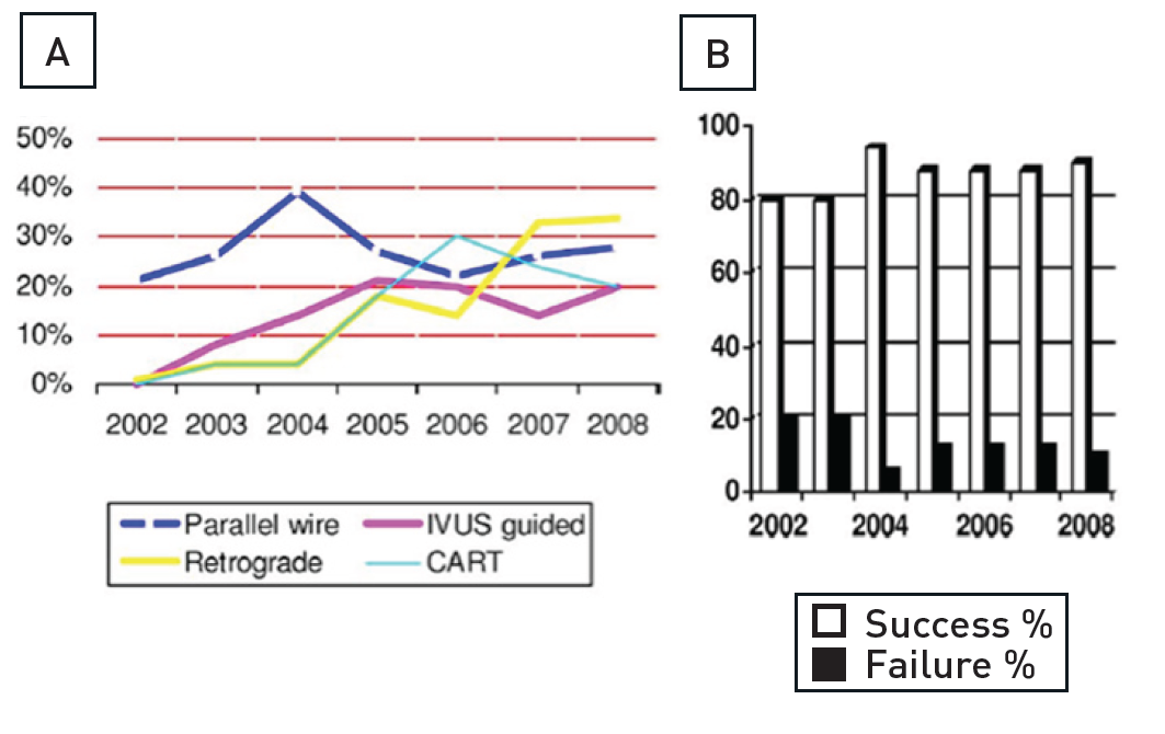
(A) Yearly increase in specific wiring techniques and retrograde approach. (B) Procedural success rates in percutaneous coronary intervention for chronic total occlusion with an increase when comparing success rates (2002 to 2004 vs. 2004 to 2008). CART - controlled antegrade and retrograde tracking; IVUS - intravascular ultrasound [from ].
There are several general considerations for the planning of a CTO procedure. A staged approach is often a reasonable strategy in multivessel disease in order to avoid excessively long procedures. Consideration of which artery to tackle first, the CTO or the non-occluded vessel(s), should be based on the importance of the occluded vessel (if the vessel and the amount of viable myocardium is important, the CTO should be approached first, while with poor contralateral flow or an intended retrograde approach the stenosis in the contralateral vessel may need to be treated first). Additionally, inverted collateral flow through the recanalized CTO may protect myocardium at risk during treatment of high risk complex lesions in the collateral donor vessel. It is important that each case is considered individually and carefully, and the consequences of success or failure of the individual lesion treatments be taken into account.
In acute coronary syndromes, the use of a staged procedure with immediate initial treatment limited to the culprit artery is often easier and clinically sound. There is no doubt that in ST-elevation myocardial infarction, treatment should be limited to the culprit infarct-related vessel and all other lesions, especially CTOs, should be referred for subsequent evaluation and possible treatment depending on evidence of ischaemia and viability. Furthermore, patients who receive glycoprotein IIb-IIIa inhibitors during a procedure for an acute syndrome should not undergo CTO revascularisation with this non-reversible potent antithrombotic agent on board.
If we assume that less than 10% to 15% of the total PCIs attempted are CTOs and we recommend a minimum number of 50 CTO cases per year to maintain competency, a large volume laboratory with more than 1,000 interventions per year can provide continuous training to no more than 2 to 3 operators. The current trend to allow low volume centres to start an interventional programme to reduce in-hospital waiting time and to allow patients to have local access to acute procedures such as primary angioplasty, often creates centres with a workload and patient mix such that no operator can perform a sufficient number of CTO procedures to maintain acceptable competency. Transferring the patient to a larger centre or developing a programme of proctorship with guest operators coming to help for the most complex cases are possible solutions. Absence of surgical back-up is not, per se, a contraindication to develop a CTO treatment programme but the appropriateness of indications must be confirmed by the regular involvement of cardiac surgeons as and when required, and the centre must confirm it has the ability to deal promptly with complications such as cardiac tamponade, as well as the safe and rapid transfer of the few cases who potentially require emergency cardiac surgery.
The availability of high quality digital flat panel detectors, a sufficient variety of guiding catheters and wires, including dedicated wires, and the possibility to use multiple balloons and drug-eluting stents to cover the entire occluded segment are required for centres willing to maintain an active CTO programme. Biplane imaging, availability of IVUS and of the Rotablator® (Boston Scientific, Natick, MA, USA) are desirable additions for CTO recanalization, but cannot be considered indispensable.
In Europe, specific training in interventional cardiology is not required in all countries and most new specialists commence interventional cardiology upon completion of their training with limited theoretical knowledge and often only modest practical experience. It is important that all angiographers understand that occlusions require acquisitions in multiple views, that the acquisition must be prolonged to visualise the distal segments filled by collaterals and that the source of collaterals must be optimally and selectively engaged (for example the conus branch for LAD occlusions, the LIMA for RCA occlusions) .
The European Association of Percutaneous Cardiovascular Interventions (EAPCI) published, in 2005, a Curriculum and Syllabus to establish an optimal homogeneous pattern of training in Europe . This curriculum had been recently updated . After a 2-year training period the candidate is expected to tackle complex angioplasty as primary operator and CTOs are mentioned as part of the experience required. We believe that all centres involved in the training of interventional cardiologists should be engaged in a regular programme of CTO recanalization. The growth in frequency and success rates in treating CTOs in Europe is critically dependent on a robust initial process of training offered to all interventional fellows. The training experience should be sufficient to overcome the steepest initial phase of the learning curve, allowing the trainee to comfortably approach at least the simplest CTOs with the appropriate equipment and strategy to achieve success, and to have gained sufficient knowledge and experience to stop before complications occur or, in the worst scenario, to treat efficiently the most common specific problems.
It is proposed that CTO procedures are part of the 200 angioplasty package required to complete the training successfully , but this depends on the qualification of the training centers. So called standard centers may not have a CTO program running, while advanced training centers must provide such a specialized program , . The role of the trainee can be variable, based on the complexity of the CTO procedures performed, and the level of training reached. It makes no sense that a trainee with less than 6 months experience in angioplasty and who may still be experiencing problems in crossing simple subtotal stenosis should face the subtleties of wire handling in difficult CTOs, but they can certainly benefit from a role as secondary operators in these complex CTO cases. For each trainee a complete logbook should indicate in detail the CTO anatomies and techniques the candidate has been exposed to, and the supervisor should give a specific evaluation of the level of training reached in CTO recanalization.
The advances of interventional therapy for CTOs over the past decade, and even since the first print edition of this chapter, are remarkable. The challenge for the experienced operator is now to choose the most appropriate strategy for each type of lesion. The ultimate goal should be to treat the patient successfully in one treatment session, and, thus, choose that approach with the highest likelihood of success, and switch to alternative strategies in case of failure of “plan A“, and ideally have further options available. It is recommended not to linger too long with a failing technique and be ready to switch options quickly. However, there may be anatomic situations where only one approach is likely to succeed, such as a retrograde option, and then the necessary time needs to be invested to achieve the collateral passage. To apply such a versatility in the approach to CTO PCI, the expertise and knowledge is required of all basic and advanced techniques discussed in the subsequent parts of this chapter.
The choice of the primary and secondary strategy, and additional alternatives depends on the operator’s skill and familiarity with different approaches and devices (Figure 42). In the US the so called “hybrid approach” has been advertised as one that incorporates a liberal use of dissection-and-re-entry by the StingRay catheter in about one third of cases , . In countries with less commercial penetration of this device the retrograde approach is favoured as an early alternative route in case of antegrade wire failure. Also, the use of IVUS as a tool to help redirect a wire from the subintimal path or even avoid such a route by identifying the proximal entry point will not be familiar to every operator.
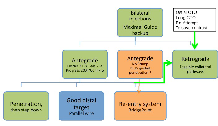
Technical options for the recanalisation procedure, according to the appearance of the proximal cap and length of the occlusion. An antegrade approach is nearly always preferred and attempted first, but according to the progress of the procedure, alternative options should be chosen like the retrograde approach or the antegrade dissection-re-entry devices. In some case, the retrograde approach might be chosen as the primary strategy.
A synthesis of both the dissection-reentry option and the more wire-based approach developed in Japan with a specific focus on the possibility of parallel wiring with new more controllable guide wires is incorporated in the so called “Asian Pacific algorithm” and the recently puplished “EuroCTO algorithm” in the updated consensus paper of the EuroCTO club . These algorithms in general aim to provide decision trees based on anatomic features of the CTO combined with the availability of collateral pathways as potential interventional routes. In order to determine the optimal strategy, the major perquisite is the optimal visualization of the occluded vessel anatomy as well as the collateral donor vessel.
The complication rate, inherent to a regular PCI, is not smaller when a CTO is attempted . Although the artery is already occluded at the beginning of the procedure, considerable damage could be inflicted on the supplying collaterals during the procedure, with ensuing infarction, similar to an acute occlusion during a procedure in a non-occluded artery.
A CTO is a lesion where the distal segment is not clearly visible, and the actual course of the vessel is completely obstructed and cannot be readily assessed from angiography especially in long occlusions. To cross a CTO we need to visualise the distal segment in order to check the position of the guidewire, and we often need to resort to more rigid wires than in non-occlusive lesions. The latter are associated with a potential to damage to the arterial wall, deviate into the subintimal vascular space, or even perforate towards the pericardium, which requires special emphasis on control of the wire progress during every step of wire manipulation.
The absolute prerequisite for a CTO procedure is to reduce risk and avoid complications. The indication is a mere symptomatic one, as prognostic considerations are not backed by a randomised study. Therefore, the CTO procedure must not harm the patient in any way, and one must be absolutely sure where the tip of the wire is positioned.
The basic requirement for a successful CTO procedure is to provide enough guide catheter support for wire and device passage of a lesion. This can be achieved by using large guide catheters of 8F, which require generally a femoral route if not sheeth-less guides are used transradially. However, the development of radial access including the smaller outer diameter of so-called slender sheaths make it possible to also use even regular 7F catheters for both antegrade and contralateral access routes. Therefore, a trend of the past years is to combine radial and femoral approach or even use a biradial approach. By using aggressive catheter shapes and/or support techniques as described below, the procedural success might be equivalent to the femoral route in experienced hands . The radial approach is in any way an alternative access in patients with severe peripheral artery disease. The main concern will remain with ostial RCA lesions where the use of a special backup catheter is denied and a larger 8F catheter combined with a long access sheath will provide the best possible backup.
The angiographic appearance of the occlusion may help decide the initial strategy. When faced with a flush ostial occlusion of the RCA, the left anterior descending (LAD) or left circumflex artery (LCX), this is one of the undisputed situations where the retrograde approach via collaterals should be considered as the primary strategy. In all other situations the CTO can be approached by the antegrade approach as the primary strategy. Different angiographic shapes with a tapered entry, a blunt occlusion or a side-branch without clear identification of the entry into the occlusion cap need to be recognised (Figure 12).
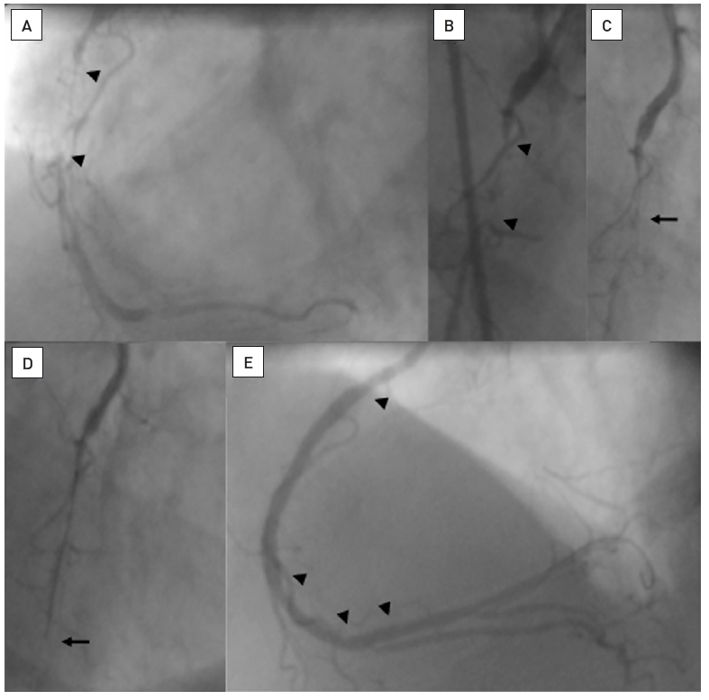
Examples of angiographic occlusion morphology
Cases A-C with tapered entry: (A) was successfully crossed with a Fielder XT as the initial choice; (B) was tried with a Fielder XT, but was not crossed to the distal lumen, and wire step-up was necessary (Miracle 3G, Confianza Pro 9); (C) Fielder XT and Miracle 3G could not penetrate, but a Confianza Pro 9 did. Cases D-F with blunt entry or side branch takeoff: (D) penetration was achieved with Progress 200T after Fielder XT failed; (E) penetration was achieved with Confianza Pro 9 after Fielder XT failed; (F) was penetrated by Confianza Pro 9 initially but went subintimal, this case was solved after switching to the retrograde approach.
In addition, to visualise the proximal anatomy of the CTO, it is mandatory to visualise the distal segment so as to obtain an idea of the course of the vessel within the invisible occluded segment. The length of the occlusion is often misjudged, and a simultaneous coronary injection will elucidate the situation (Figure 13). A second sheath for injection of contrast to visualise the collateral filling from the contralateral artery is always mandatory except in those cases where we have ipsilateral collaterals filling the distal lumen. However, antegrade wire progress may occlude this ipsilateral collateral source, and then contralateral injection is needed for visualisation. Therefore, in the latter case, the second access site should be prepared, and the second sheath inserted immediately should distal visualization from ipsilateral collaterals be lost. For an antegrade recanalization approach it is often sufficient to use a small diagnostic sheath (4 Fr or 5 Fr) for the contralateral visualization. Larger diameters will increase the contrast use during the procedure but are sometimes required to visualize small collateral connections which become visible only with adequate contrast injections.
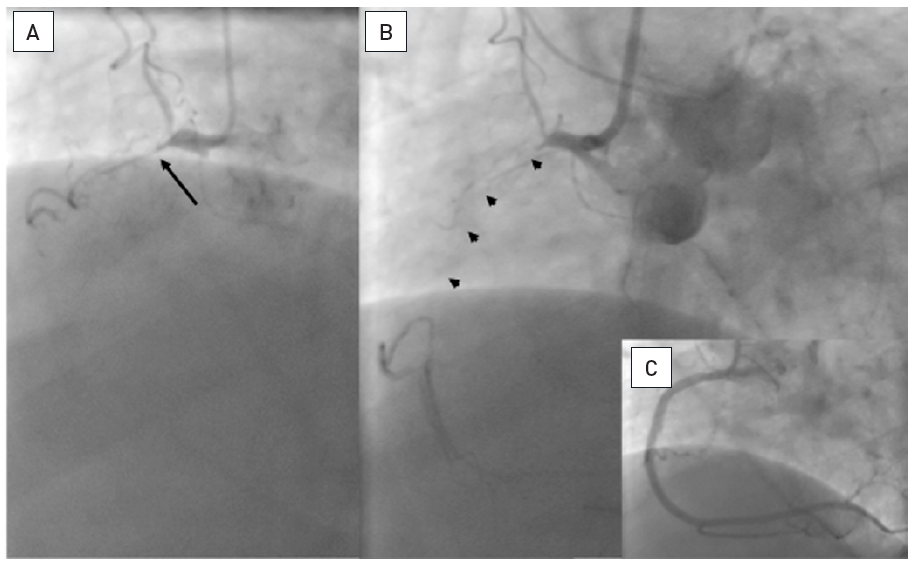
Proximal occlusion of the RCA with tapered entry (arrow), but no information on the length and presumed vessel course from the antegrade injection (A). Only the simultaneous bilateral injection reveals the length and direction of the occlusion (arrow heads, B). (C): Result after antegrade recanalisation.
Intracoronary injection through microcatheters is not advised, if positioned in the subintimal space, as this will lead to contrast obstruction of the true lumen and dissection and make further progress futile. However, there is no rule without exemptions, and in cases of poor visualisation via collaterals or within a long-occluded segment and unexplained lack of progress, a gentle injection through the microcatheter may be tried if blood can be aspirated indicating an intraluminal position. If no blood is aspirated, the injection is most likely directed into the subintimal space, which is discouraged as it obliterates the true lumen even more, and the procedure might need to be stopped. There are reports that an antegrade injection into the occlusion through the microcatheter may facilitate the wire recanalization , but the reported success rates with this approach are low as compared to current standards .
Intracoronary injection through microcatheters, however, may be a valid method to visualize the distal coronary segment by advancing the microcatheter in one of the collaterals that supply the distal coronary bed. Thus, the amount of contrast medium needed to visualize the target segment is vastly reduced as spill-over into the the donor artery is avoided as 1 cc might be enough to achieve sufficient contrast filling. Especially in situations when a collateral supplies the LAD from the LCX and during the recanalization procedure antegrade injection into the coronary bed is not adsvised because of propagating a possible dissection, the selective microcatheter based injection into the collateral can help avoid such a complication.
At the beginning of the procedure, we must ensure that there is sufficient guide catheter back-up not only for the wire passage, but also for subsequent balloon and stent advancement. Especially for the RCA, the regular right Judkins guide may not provide adequate support. However, there is a balance to be made between catheter size and shape, and this requires careful planning right at the start of the procedure. A large diameter, such as 8 Fr, will provide enforced support even with the less aggressive regular Judkins right curve, and it provides ample working space for complex techniques of double wires, anchoring balloon, intravascular ultrasound (IVUS) guidance etc. This approach is especially important for proximal or ostial occlusions, where deep guide engagement is not possible or counterproductive. For lesions close to the ostium of the RCA, a proper alignment of the guiding catheter with the vessel course is crucial (Figure 14), and this may not always be achieved with a Judkins shape. An alternative in this instance could be an internal mammary guiding catheter. In non-ostial lesions a smaller guide size of 6 Fr will require deeper engagement for adequate support. This can be ideally achieved with a left Amplatz 1 or 0.75 curve. It is important for the RCA to always use catheters with side holes, to avoid local dissections during contrast injection into the occluded proximal artery.
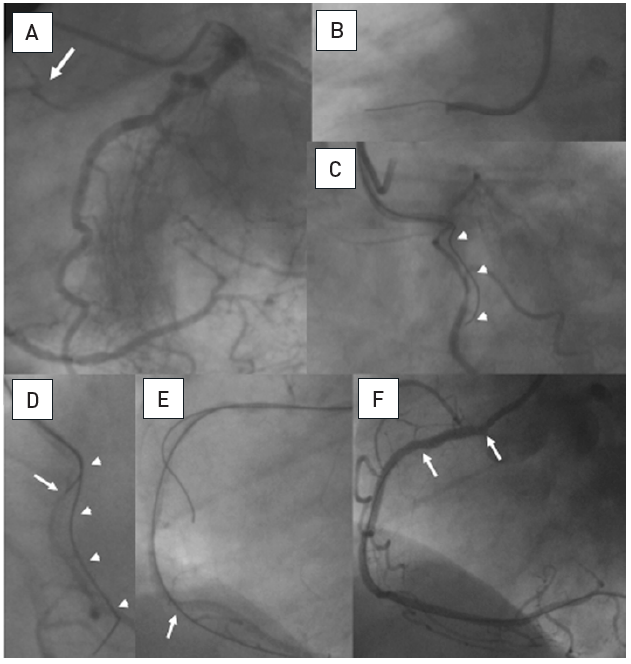
A. Short RCA occlusion located right at the ostium (arrow), well collateralised from the left coronary artery. B. Difficult and imperfect seating of a guiding catheter (Amplatz right 6F) with a Miracle 3G (ASAHI Intecc). C. The RAO view cranial angulation shows the paravascular wire position, however, this wire now served as an anchor for the guiding catheter, which enabled a better alignment towards the true vessel course. D. With realignment due to the advanced first wire, a second parallel Miracle 3G wire is now advanced with a better angle to the true lumen (arrow). E. Now the second wire is clearly intraluminal as verified with repeated contralateral injections and further advanced distally, where it entered a side branch (arrow). F: After balloon dilatation and a singular Taxus stent (between arrows) perfect antegrade flow is re-established.
For the left coronary artery, the guide catheter has to be selected according to the length of the left main artery, and the angle of take-off of the occluded artery. Given that CTOs considered worthwhile for treatment will generally be located in the main arteries, recanalization of the left anterior artery (LAD) may be well supported by an extra backup shape, while occasionally the classic Amplatz left 2 or 3 shapes may be ideal for proximal LCX occlusions.
The operator needs to know methods to enhance the backup with a buddy-wire, or with anchoring balloons , . They are intended to improve and stabilise the guide catheter position in the ostium. In order of increasing complexity, the respective methods are:
An efficient technique is the anchoring balloon (Figure 15). A floppy wire is inserted into a side branch proximal to the occlusion, and then a balloon of sufficient size is advanced into this artery. Under sizing would lead to slipping out of the balloon and may cause dissection. The balloon is then inflated to 8 to 10 atm and kept in position during manipulation, balloon passage and stent placement. Arrhythmias due to the balloon inflation are rarely seen, but if present would then require intermittent deflation. In general, complications due to anchoring in RCA side branches are unlikely. Using the anchoring in larger side branches of the left coronary artery may of course lead to ischaemia. In the left coronary artery, a stiff buddy wire in one of the larger arteries like an Ironman™ (Abbott Vascular, Redwood City, CA, USA) may increase the support sufficiently even without balloon anchoring.
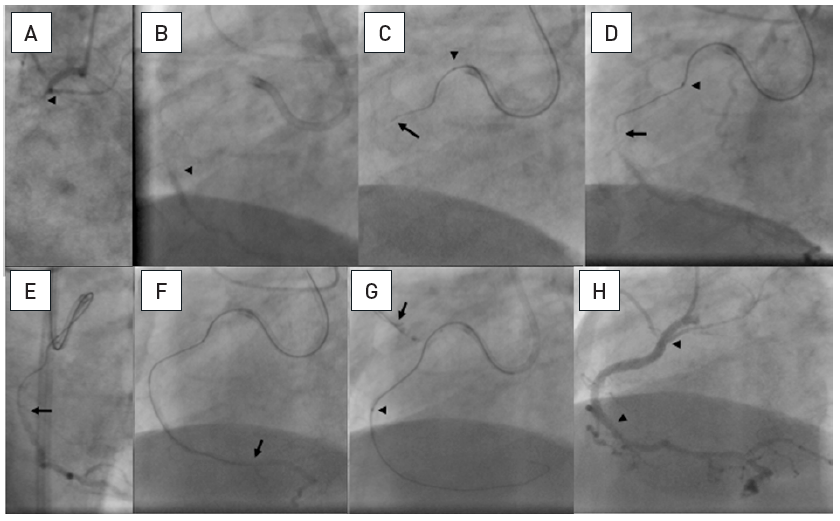
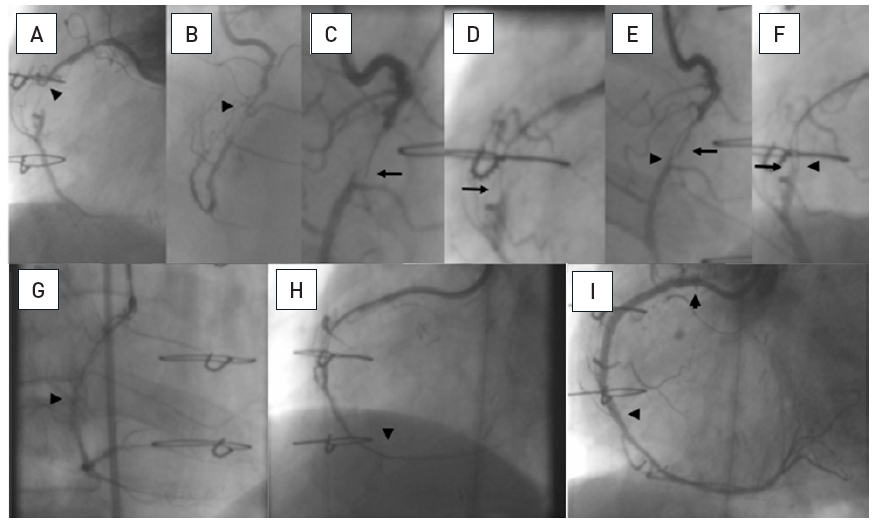
A 20 mm long occlusion of the proximal RCA with a tapered entry (arrow head, A), and the distal target beyond a bend (arrow head, B). Sequence shown in clockwise direction. A 6 Fr Amplatz left 1 side hole guide is used. Despite angiographic signs of calcification ©, a Fielder XT wire (arrow) is advanced relatively easily far into the occlusion supported by a FineCross microcatheter (arrow head).The wire is advanced gently further around the vessel bend towards the distal target (arrow, D). Entry into the distal lumen is verified in RAO (arrow, E) and orthogonal LAO views, and advanced further (arrow, F). The calcification of the vessel with a sharp bend prevented the advancement of a low-profile balloon. This was overcome by an anchoring balloon in a proximal side branch (arrow) which enabled the progress of the balloon (arrow head, G). Subsequently further balloon dilatation and stent placement (between arrow heads, H) was accomplished with the help of the anchor balloon.
More recently the use of guide extensions has become more popular as they do not require an adequate anchor vessel and can be advanced deeply into the vessel if required . They can support both the passage of the wire, the passage of a device and they are helpful in the retrograde approach to facilitate the retrograde wire passage. In order to advance a aguide extensions deeply into the coronary artery it is advisable to use a balloon as a rail and to advance slowly with repeated balloon inflations distal to the guide extension, and while deflating advance the guide extension across the balloon (inchworm technique) .
The use of a support catheter or microcatheter with an over-the-wire (OTW) technique is strongly recommended as it facilitates wire manipulation greatly (Table 1). OTW balloons would be an alternative provided the tip diameter is low. However, the tip marker of the microcatheter is very close to the tip and identifies its position, whereas in OTW balloons the marker is >10 mm from the tip so that the tip position within the occlusion is not absolutely sure. The physical property of the balloon itself impairs the flexibility of the tip, whereas a microcatheter shows a uniform behaviour of the tip. The lumen within a microcatheter is slightly wider than that of an OTW-balloon, which improves wire manipulation with less friction (Figure 16).
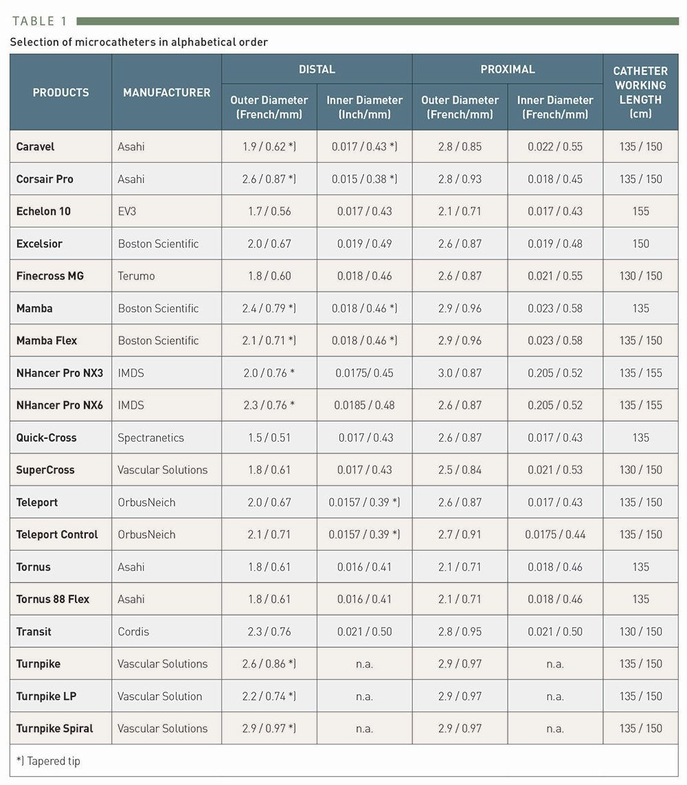
Selection of microcatheters
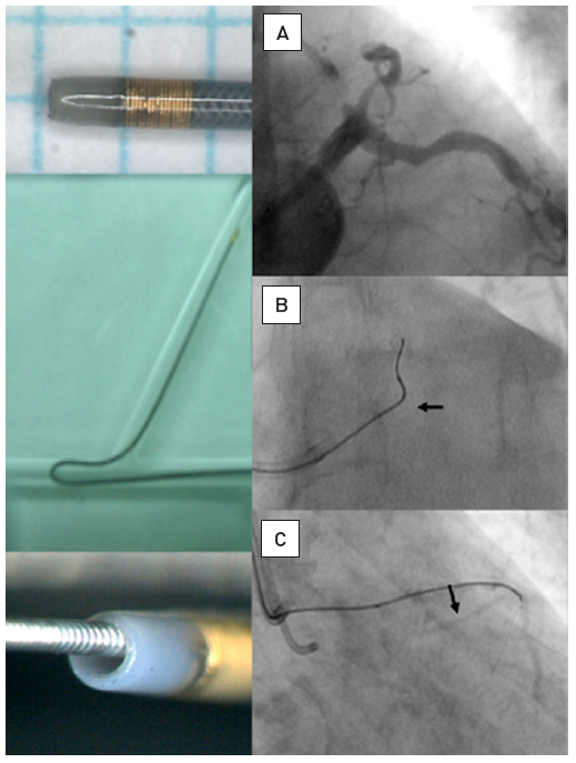
Example of a modern microcatheter FineCross MG [Terumo] with a braided shaft and tip
The tip marker is positioned close to the distal tip which is tapered for better entry profile. The inner lumen holding the guidewire is larger than in an OTW-balloon; the braided shaft prevents kinking. Application of a microcatheter: (A) Proximal occlusion of the LAD, the distal target filled by simultaneous injection through bilateral injections. (B) To enter the proximal segment, a sharp wire angle is required. With this, the microcatheter (arrow) is advanced proximal to the occlusion. (C) Then the wire tip is reshaped and the wire (Miracle 3G) advanced safely into the distal true lumen as visualised by contralateral injection.
A sharp angled take-off of the occluded artery from the left coronary artery may require soft hydrophilic wires to negotiate it, whereas the required angle and the wire stiffness will be inadequate to pass the proximal cap of the occlusion. After advancement of a microcatheter to the proximal end of the CTO a softer wire can then be exchanged for a dedicated recanalization wire without risk to the protected proximal segment.
An important issue during advancement of a recanalization wire is the need for different tip shapes during the course of wire advancement, and also the preservation of the tip shape which may get lost during a lengthy procedure and needs to be modified or corrected. This can be easily checked and done with the help of a microcatheter which is advanced into the proximal part of the occlusion or, in the case of long occlusions, deeper into the occlusion.
Besides the straight low-profile microcatheters, there are some support catheters with specific designs to help wire manipulation or which may be of assistance during the further course of a recanalization procedure. One is the double lumen design, where one wire is guided through a central lumen in typical OTW fashion, and a second wire port exits further proximally, with a shorter rapid exchange lumen (Twin-Pass® [Vascular Solutions Inc, Minneapolis, Minnesota, USA], Crusader™ [Kaneka Corp, Osaka, Japan]), FineDuo™ (Terumo Corp., Tokyo, Japan), Sasuke™ (ASAHI Intecc, Aichi, Japan). Another support catheter is the Venture™ catheter (Vascular Solutions Inc, Minneapolis, Minnesota, USA) with a flexible tip that can be manipulated through a torque mechanism from the distal port of the catheter. This should enable the operator to align and centre the wire towards an ostial occlusion of a side branch, for example a sharp take-off of an occluded LCX. While the alignment may facilitate wire entry, the catheter is generally too bulky to be advanced across the occlusion in the manner of a low-profile microcatheter. Other support catheters like the Tornus®, Corsair (both ASAHI Intecc, Aichi, Japan), and Turnpike™ (Vascular Solutions Inc, Minneapolis, Minnesota, USA) are discussed later.
With the above-described approach to CTOs, after successful wire passage, the OTW catheter or balloon needs to be exchanged for a first or subsequent balloon for dilatation. This can be achieved by the use of long wires from the beginning, or by dedicated extension wires. However, not all wires are available in 300 cm length, and not all extension wires fit all wires, and are not therefore universally applicable. One technique to overcome this problem is the flushing out of the microcatheter. This is easily done with a FineCross™ (Terumo Corp., Tokyo, Japan) or similar microcatheter, but may not always be easily achieved in the case of guidewire kinking or multiple wires within the guide catheter. The simplest method is just to place a 10cc saline filled syringe on the distal tip of the microcatheter with the distal 1cm of the wire protruding. Then with manual force the syringe is compressed leading to release of the microcatheter without moving the guidewire. The manual force can be reduced once the catheter is moving. If this does not work, a balloon inflation device can be attached to the distal end of the microcatheter, and under increasing pressure, up to 20atm, the catheter can be released. If this does not lead to active movement of the catheter, it can be gently retracted under control of the wire position. The wire is held in position by the pressure exerted on the microcatheter.
In case this does not work, or the operator is not sure about the security of the distal wire position, the safest way to exchange a wire is the “trapping technique”: the microcatheter or OTW balloon is moved back as far as possible until the distal 1cm of the guidewire is protruding from its end. Then a balloon catheter is advanced without the need for a separate wire parallel to the microcatheter into the guide catheter to be positioned distal to the distal end of the microcatheter, but within the guide catheter, usually within the distal 3 to 4 cms. This balloon is inflated at 10 to 12 atm thus trapping the guidewire distal to the microcatheter, while the microcatheter can be safely retrieved without losing the wire position (Figure 17). To achieve a sufficient trapping effect, a 2.0mm balloon is required for a 6 or 7Fr guide and a 2.5 mm balloon for a 7 Fr or 8 Fr guide. This technique should also be used to secure a stiff bare guidewire when a microcatheter needs to be advanced over this wire without the risk of inadvertent distal advancement of the wire.
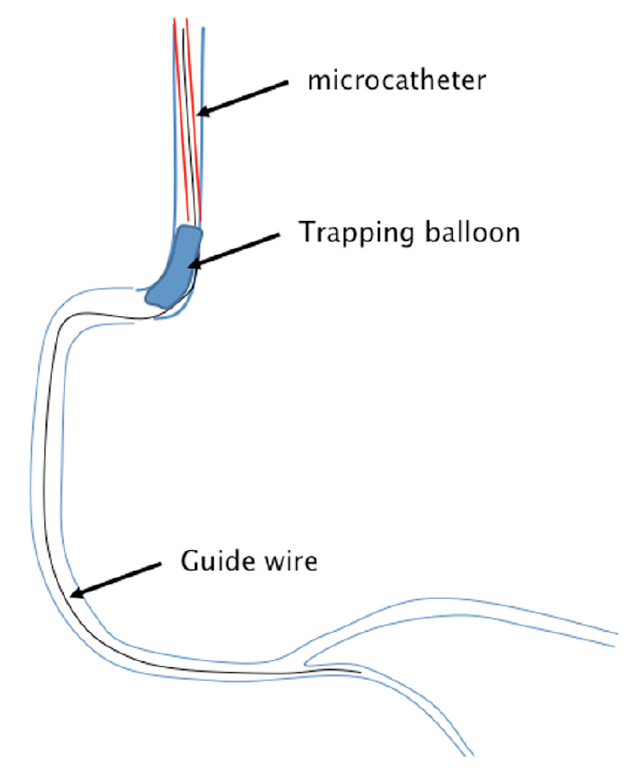
Schematic presentation of the trapping technique
A guidewire is passed into the coronary artery supported by a microcatheter. To remove the microcatheter without losing the wire position, the microcatheter (red) is pulled back into the guiding catheter. A balloon catheter (blue) is advanced without a wire beyond the microcatheter, and is then inflated inside the guiding catheter. Thus the wire is trapped and does not move back once the microcatheter is completely pulled out.
A problem with this technique might be when the trapping balloon is not mounted on a wire but advanced barely, that with low visibility of the radiopaque markers of the balloon, the advancement might be missed on fluoroscopy and the balloon pushed beyond the guide catheter tip into the coronary artery. To prevent this, special trapping devices were developed and are available for both 90 and 100 cm catheter lengths (Trapper™, Boston Scientific, Natick, MA, USA; Trap-It™, IMDS, Roden, The Netherlands).
One should keep in mind that multiple wire and balloon exchanges and the above-described techniques may lead to a considerable loss of blood through the Y-connectors during the course of a long procedure. Y-connectors designed to reduce blood loss are available and should be preferred.
Guidewire selection incorporates a great deal of personal preferences and experience. For a detailed description of available wires see the recently updated EURO-CTO Club consensus document , however, wires are continually developed and improved. There is no single wire that serves all lesions and all circumstances, and a familiarity with several wires from each family is mandatory. Different operators may prefer different wires and still achieve the same final success, nothing is more important than the predictability of the wire movement which comes with familiarity with the wire of your choice. Still there are some general rules to wire selection, which are accepted by the majority of operators. One feature to differentiate wires is the construction principle of a spring coil wire or a PTFE coverage, also labelled plastic-jacket wire (Table 2a and Table 2b), but there are also wires which incorporate both principles like the PROGRESS wire family (Abbott Vascular). Recently, ASAHI Intecc (Nagoya, Aichi, Japan) introduced a new family of wires based on a new tip construction, the dual-core design, which enhances the torque control of the wire tip, and many new variations of this design in new wires had been released. An additional new brand of wires was introduced by Boston Scientific with their range of Fighter, Samurai and Hornet wires of various tip strengths.
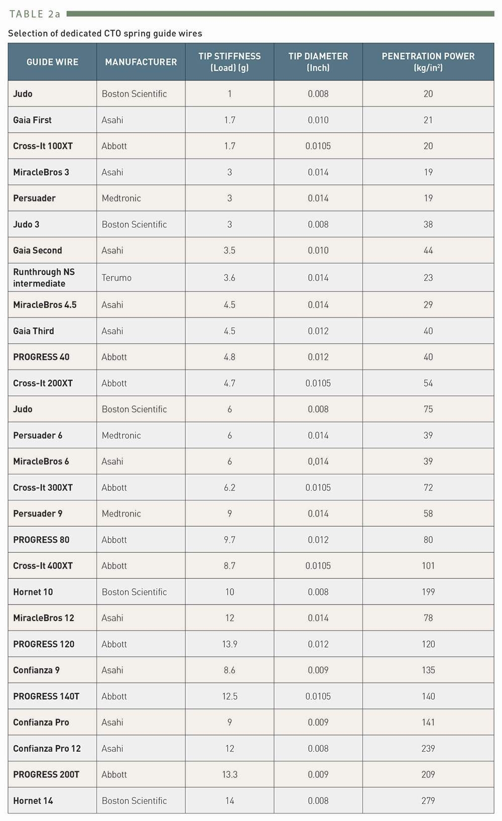
Selection of dedicated CTO spring guidewires
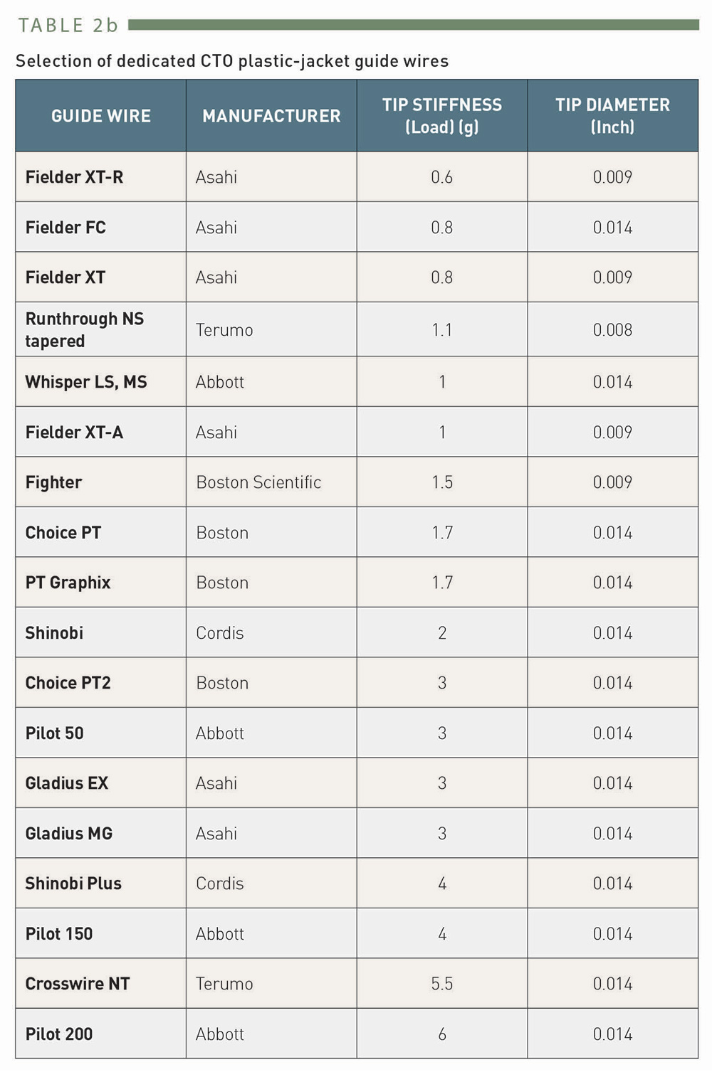
Selection of dedicated CTO plastic-jacket guidewires
In general, for CTO recanalization, three features of the guidewire are of utmost importance, the tip stiffness or penetration force, the ability to shape the tip and retention of the shape, and above all the torque control. Penetration force is a combination of wire strength and tip diameter, it is greatly increased with tapered tip wires (Table 2a). Wires may be used in incremental fashion with increasing tip stiffness when the previous wire encounters resistance. The torque control is a major feature of dedicated CTO wires in order to facilitate manoeuvring of the wire in long resistive lesions.
The wire selection depends on the planned approach to the occlusion, which is determined by the angiographic features of the lesion. Initially, three technical approaches are discriminated, the “drilling technique”, the “penetrating technique”, and the “sliding technique”. Each of them may be selected from the onset according to the angiographic appearance of the occlusion and knowledge of the occlusion length, but often needs to be changed during the procedure. Flexibility and adaptation of wire strategies is required throughout the whole procedure (Chapter 3.1).
Before the wire is advanced, the tip has to be shaped. This is the first and basic step of wire manipulation, and often requires modification during the progress of the procedure. In non-occlusive lesions a basic rule of thumb is to adapt the radius of the tip angle to the size of the artery in which the wire is to be advanced. A major difference with tip shapes in CTOs is that the vessel diameter at the lesion site is practically zero. Therefore, the length of the proximal tip angle is as short as possible with a moderate 30° to 45° angle. A secondary angle is added about 5 mm distally to enable wire manipulation in the vessel segment proximal to the occlusion, and to facilitate the tip engagement. These considerations apply in general to all wire types and techniques in CTOs (Figure 18).
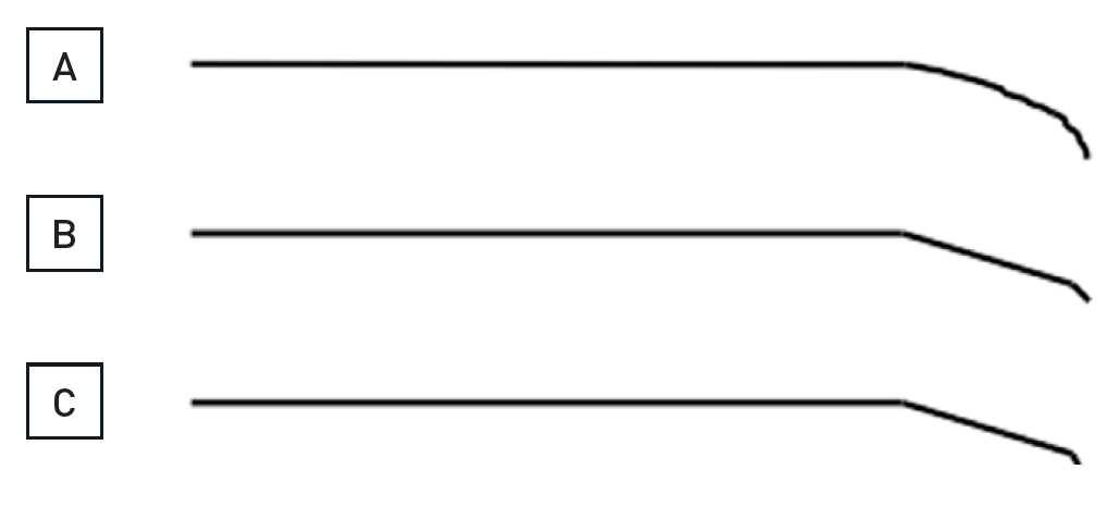
The shaping of the wire is crucial for a successful passage through an occlusion
The wire shape needs to be modified during the different stages of a procedure. A rounded (A) or more angled shape (B), the latter with a more pronounced distal tip angle of about 30° over the last 1mm to 2 mm of the wire, and a more proximal 30° secondary angle will serve many situations. For distal re-entry manoeuvres, or during a parallel wire approach, a more pronounced distal tip angle might be needed (C).
The drilling approach is ideal for occlusions with a distinct entry point. Typical wires for this approach are moderately stiff wires with high torque-control such as the Miracle Bros family of wires (ASAHI Intecc). The tip diameter of these wires is 0.014” like normal workhorse wires, but the enforcement of tip strength is incremental. The 3G wire provides more push than a softer floppy or PTFE wire (Figure 19). Before the wider popularity of the Fielder XT wire (ASAHI Intecc) see below, this was the initial wire of choice for many operators. A further development of this type of wire is the Ultimate, which is comparable to the 3G, but due to a hydrophilic coating its penetration ability seems to be enhanced.
A patient with a 25 mm occlusion of the proximal RCA (A and B, between arrow heads). Initially a Fielder XT was tried and advanced into the occlusion as far as shown on C (arrow). Despite the support catheter, the wire could not advance further. Thus, a Miracle 3G was exchanged and could then be advanced beyond the distal occlusion cap (D, arrow), the position was verified by contrast filling. The angioplasty required stenting of the occlusion (E, top arrow heads), but also treatment of the distal RCA bifurcation (arrow heads).
With increasing strength of the wires from 3G to 12G or even 14G with the Hornet family the pushing force could be adapted to the requirements of the lesion in case of problems with wire progress. The wire strength cannot be increased by the aforementioned microcatheters, but the ease of manipulation will be improved as the friction within the catheter is lower than within a long proximal arterial segment. The wire handling with drilling consists of a very slow advancement of the wire into the occlusion with a turning movement on the torque handle of less than 90° degrees in each direction in alternative directions. A new way to increase the wire penetration force is achieved with a dual-lumen catheter mounted on a primary wire that might be positioned in a side branch or went in a subintimal position, and a secondary wire is advanced through the OTW lumen of that catheter.
The penetrating approach is ideal for occlusions without any discernible entry point, typically at the site of side branches. The penetration requires smaller tip wires such as the Cross-it or more recent Progress wire family (both Abbott Vascular) with 0.010" or less tip diameter, or the classic Confianza or Conquest family of wires (ASAHI Intecc) with 0.009" tip diameter. A similar feature has the more recently introduced Hornet 14 wire (Boston Scientific) with nominally the highest tip load of 14g among the coronary wires in Europe. These wires provide increasing tip stiffness, and, except for the wire tip, with additional hydrophilic coating to reduce friction of the wire and enhance the penetration force. In Japan even stiffer wires had been on the market for some time like the Conquest Pro 8-20 upto 8-40. These wires are available as dedicated peripheral interventional wires even in Europe under the name Astato XS® (ASAHI Intecc). Penetration into the subintimal vessel space with these increasing wire stiffness may be frequent and therefore requires careful monitoring and control of the wire approach.
The sliding technique rests on the low friction advancement of PTFE wires and is ideal for occlusions with suspected residual lumen or occlusion duration of less than 6 months. These wires are widely (over)used, as they promise a fast approach because of the low friction, but the steerability is limited especially with the Pilot™ (Abbott Vascular) and ChoICE® (Boston Scientific) wire family and will easily leave the vessel lumen. However, in experienced hands they can be used gently and carefully as an alternative approach and will also be successful in crossing even complex looking occlusions. Arguably their more effective use is as a step-down option, once the proximal occlusion cap is passed e.g., by a Confianza wire, and the softer distal occlusion poses resistance to the advancement of the shafts of the rigid wires, not to their tips. Exchange over a microcatheter is ideal in these cases (Figure 21). A recent addition to this type of wires is the Gladius® wire which may improve the torque control through the so called ACT ONE® technology (ASAHI Intecc). It cannot be emphasised enough that no single technique serves all lesions, and all approaches should be utilised and combined as required.

Long occlusion of the RCA with a diffusely diseased narrow segment proximal to the occlusion and a tortuous distal target segment (arrowheads A, B). Sequence shown in clockwise direction. A parallel wire approach is chosen, after the initial Miracle 3G wire got stuck (top arrow, B), and a second Confianza Pro 9 could be advanced further, but is now below the distal target (bottom arrow, B). Repositioning of the Confianza wire allowed entry into the distal lumen (arrow, C). With this stiff wire, however, the sharp angled distal tortuosity cannot be negotiated. A step down approach is required. The wire is placed in a distal side branch (arrow, D), to enable a low-profile balloon 1.25mm to be advanced after microcatheter exchange. After balloon dilatation, a microcatheter (QuciCross, Spectranetics, showing three markers, the distal is indicated by the arrow head) is reinserted and advanced distal to the occlusion (arrow head, E), and a soft PTFE wire (Whisper LS, Abbott Vascular) is then advanced distally (arrow, E and F). After balloon dilatation four DES are required to cover the diffusely diseased artery (arrow heads, G).
The family of Gaia wires with the dual-core design and a unique pre-shaped miniature tapered tip provide an additional dimension to wire manoeuvrability within CTO lesions. The principle of handling these new wires with different wire tip strength between 1.7 and 4.5 g is based on visual control of the wire tip on the fluoroscopic image rather than rely on a tactile feedback. The torque control of these wires is close to 1:1 and allows a redirection within the CTO body that is more controlled than with previous wires. Many operators have included these wires already in their preferred wire choice for both the antegrade and retrograde approach. The further development of this family of wires is labelled Gaia Next (ASAHI Intecc) already available in some parts of the world. These wires have an even more intricate design to improve torque control, and an increase in tip strength over the initial Gaia wires.
A new development of the initial wire selection was inaugurated by the Fielder XT wire (ASAHI Intecc), which deserves a special mention. (Table 2b). Similar wires are now under development or available from other manufactures. The Fielder XT consists of a PTFE coating, but the core provides a high torque control and the tip is tapered to 0.008”. The tip welding is extremely short, allowing very short distal wire curves. It is very delicate and should be advanced even slower and more gently than a regular PTFE wire like the Whisper (Abbott Vascular), Pilot , or Fielder wires. The tip shaping of this wire needs to be done very delicately and gentle as the tip may be easily damaged. Furthermore, the wire should not be pushed and buckled within the occlusion, as the tip may not be restored for a controlled guided advancement. Buckling of the wire tip is done on purpose in some subintimal re-entry techniques (see below).
The Fielder XT can be basically applied using the sliding approach, but due to the tapered tip it may also enter soft parts of a blunt proximal cap and help in the penetrating approach as well as in the drilling approach. Inside the occlusion this soft wire with its delicate tapered tip may proceed within loose tissue even in calcified lesions (Figure 15).
There was a discussion as to whether this wire works because it can probe microchannels due to its smaller tip diameter in relation to regular guidewires. However, no histological study has shown clearly traversing microchannels. Experimental studies in animal models even suggest that microchannels are a feature of early and recent occlusions but disappear in older occlusions where microchannels are unlikely to be found . A recent pathological analysis of the largest number of lesions, yet, even states that, microchannels are rarely found in CTOs . The fact, that this type of wire works so frequently as the first and finally successful wire is rather due to the fact that the soft tapered tip may track the loose tissue within the occlusion body and therefore traverses the CTO without exiting subintimal.
The Fielder XT has the ability to frequently provide entry into the occlusion, and many experts are currently using this wire as their first line approach. The response to this wire dictates the next increment of tip force and tip size.
This wire had been further refined by incorporating the above-mentioned dual core design with the Fielder XTA and the Fielder XTR, the latter with a reduced tip force also suitable for residual antegrade channels, and it can navigate safely tiny collateral channels.
The application of the wires in a sequence from low tip load for exploring the proximal cap to increased stiffness in case of resistant caps is summarized as antegrade wire escalation (AWE) in current algorithms of CTO PCI , , . The choice of the initial wire is dependent on the anatomy of the CTO, but also on the preference of the operator. A frequent sequence would be a Fielder XT-type wire to begin with, followed by a Gaia 2 and then followed by an even stiffer wire. Once the proximal cap is penetrated and the operator can advance a microcatheter inside the CTO body there is always then the option to downgrade the wire to a softer less traumatic wire (step-up step-down technique).
When true lumen wire passage fails, the rule is not to try with a wire that went subintimal too hard and too long in order not to increase the size of the false lumen. Also avoid antegrade contrast injection and rely on contralateral injections to avoid extension of dissections. The wire tip should not be advanced beyond more than 5 mm to 10 mm extraluminal of the distal cap, but rather remain there and a second wire can be inserted for the parallel wire technique (PWT) (Figure 20).
A patient post CABG with a 15mm occlusion of the mid RCA with the proximal occlusion entry not identifiable at a side branch (arrow head A and B). Panels in clockwise orientation show the penetration of the cap and parallel wire approach. A Confanza Pro 9 wire is advanced to penetrate the proximal cap, but the tip (arrow) deviates to the anterior (C: RAO 30°) and lateral (D: LAO 30°). A second Confianza Pro 9 is advanced in parallel but with another course to correct for the malposition of the first wire, posterior in RAO (E) and more medial in LAO (F). Thus the second wire enters the distal cap, which is confirmed by contrast during wire advancement (G and H). The case is concluded with three DES shown between arrowheads.
PWT is a classic method first introduced by Drs Katoh and Reifart during a live demonstration in 1995 based on the then limited available wires, but it is still a successful addition of the strategic sequence of the antegrade approach. With modern, better controllable wires this approach should not be forgotten and remain an option in the step-wire sequence of the antegrade wire escalation (AWE).
The first wire serves as a guide to the general direction of the vessel course and may enable the manipulation of a second parallel wire slightly deviating from the initial course to successfully enter the distal lumen. Often, the first wire is a moderately stiff wire, and the second wire is of increased stiffness, or tapered (e.g., Miracle in combination with Confianza Pro). This technique can be accommodated by modern 6Fr guide catheters. However, if both wires are supported by a microcatheter or OTW balloon (then termed the “see-saw technique”) , a larger diameter of 7 Fr or 8 Fr is required. If necessary even a third wire may be introduced. Now with advent of the Gaia wires, the Gaia 2 is often used as the primary wire in these types of occlusions, and depending on the resistance within the occlusion is then combined in parallel with a second Gaia 2 or a wire of incremental strength such as Gaia 3 or Confianza Pro or Hornet 14.
The direction of the parallel wire manipulation is often misleading when looking on one imaging plane only. A frequent change of view using orthogonal planes is advised. This may be a situation where a biplane angiographic imaging with instant control of the wire position from two orthogonal views and repositioning brings a major advantage over a monoplane angiographic system (Figure 22).
About 25mm long occlusion of the proximal LCX as visualized by a simultaneous bilateral injection (arrow heads, A). A 8F AL2 sidehole guide catheter is used. A biplane angiography was used to adjust the wire advancement. The first wire was a Confianza Pro 9 supported by a Finecross microcatheter. Contralateral visualization of the distal target (arrow head) shows, that the wire deviates clearly anterior on the RAO view (arrow, B), but on the LAO view it seems to be off course only in the distal part to the lateral (arrow, b). As second wire a Confianza Pro 12 is advanced over a separate microcatheter in see-saw technique correcting the wire course according to the previous wire more posterior in RAO (open arrow, C) and with a similar course in LAO with only a more caudal course distally (open arrow, c). With these adjustments, the distal lumen (arrow head) can be safely entered as visualized in both views simultaneously (open arrow, D and d). The final result is obtained with two DES (arrow heads, E).
Deviation of the primary wire from the true vessel lumen may occur at every and any point during advancement, but often it is at the entry of the occlusion with a large side branch where the wire deviates. Sometimes, when an occlusion features several side branches, typically within the LCX with large obtuse marginal branches, the wire can be directed only into one of the secondary branches. If, after some effort, this cannot be controlled, it may be prudent to dilate the occlusion towards this side branch with a small sized balloon. Not infrequently, this manoeuvre then provides easy access to the other occluded branches and is therefore termed the “open sesame” approach.
An important concept of this approach is the fact that a first wire passed in the vicinity of the target within the vessel structure will alter the conformity of the vessel. Especially long occlusions in the RCA tend to collapse without a surrounding myocardial brace of the artery, unlike in an LAD occlusion. This collapse and tortuous course of the original vessel is altered by a first wire. The second wire then runs along a changed anatomy and conformity of the vessel. Basically the same is true when we work with two wires towards each other in the retrograde approach.
In parallel wire situations where the direction of the guidewire’s advancement is defined, but the wire will simply not penetrate the intended segment, the support of the wire needs enhancement. This can be achieved by inflating an OTW balloon proximal to the occlusion, or by using other enhancements of guide support such as the anchoring balloon technique or mother-in-child catheters.
In the past years the use of a dual-lumen catheter in this situation has gained wider use . This can improve PWT in many ways. One is that it takes away the need to navigate the proximal section were the first wire already passed, provided that the catheter can be advanced. Therefore, small diameter catheters will be preferred. Another advantage is the increase of the wire control as the dual-lumen catheter provides a much more stable position than a single lumen catheter.
There is a debate whether PWT is a re-entry technique or an approach, where the wire more likely stays inside the plaque and thus luminal. IVUS analysis of the antegrade approach from a Japanese study using PWT as a common part of their approach reveals a subintimal pathway only in 12% of the antegrade approach . The operator’s skill and experience are required to understand whether the wire will have entered the plaque luminally at the the level of the proximal cap. The wire enters correctly into the plaque, but deviates at the end before reaching the distal cap. Here the dual-lumen catheter can help guide into the already found pathway and then helps to find an alternative exit. If the proximal cap is already passed with a subintimal position, the dual-lumen catheter can help to fix the second wire in front of the cap and help to find an alternative location to penetrate the cap. The former may be more frequent in the RCA, the latter situation in the LAD and LCX.
The classic dual-lumen catheter consists of a rapid-exchange lumen which is advanced over the first wire, and the over-the-wire lumen for advancing the second parallel wire that exits on the distal side port. A new development is a dual-lumen catheter with two over-the-wire lumen and an additional alternative side-port exit for the centrally advanced wire (Recross®, IMDS). This design may facilitate the use of the first wire through the additional side port when the second wire is also beside the distal target. An alternative use of this design would be the use of a re-entry device.
One disadvantage of PWT is that to determine the wire position relative to the distal cap it is required to do multiple contrast injections into the donor vessel to verify and modify the wire progress. On a mono-plane angiographic system this requires additional shots in various angles, while on a biplane angiographic system the contrast injections will be reduced due to the simultaneous orthogonal views. In patients with chronic kidney disease PWT, if it is not immediately successful, should be not pursued, unless a visualization of the distal coronary bed cannot be achieved with reduced contrast injections such as through a selectively placed microcatheter in a donor collateral.
With the advent of the retrograde technique, one needs to determine beforehand when to switch strategies if the antegrade approach fails. The antegrade wire will remain in position when the retrograde probing starts, but one will cut the parallel wiring attempts short if an alternative route is considered possible. If there is the plan to use a retrograde approach, provided experience for that approach exists, not more than 10 to 15 minutes of fluoroscopy time should be spent before deciding to switch to the retrograde approach.
Different strategies to achieve re-entry have been developed, such as a brute force advancement of a wire loop with the aim of gaining distal re-entry, but with the high risk of shearing off possibly important side branches (subintimal tracking and re-entry (STAR) technique) , . Variations of this technique include a more limited dissection using a stiff wire to penetrate the lesion, then reverting to a soft wire, typically the Fielder FC (ASAHI Intecc) for a controlled re-entry without shearing off side branches. This approach had been developed by Alfredo Galassi and termed the mini-STAR technique.
More controlled approaches include the attempt to re-enter with stiff and tapered wires with or without the assistance of IVUS - a method with limited success; or variations of the controlled antegrade and retrograde subintimal tracking technique (CART). , , , . This requires a retrograde wire passage through collateral channels to be combined with an antegrade wire advancement, and with either proximal or distal (retrograde) advancement of balloon catheters and dilatation to create local dissections to facilitate a wire re-entry into the true lumen. Recently, an technique called antegrade fenestration and re-entry has been described which introduces the use of a balloon advanced on a wire that ends in the subintimal space, and a parallel wire advanced along. The concept is to disrupt the subintimal and luminal partition and induce a connection that would allow the second wire to be advanced into the distal true lumen . The combined antegrade and retrograde procedures in particular require long procedure times, and increased radiation.
A new family of devices (Bridgepoint Medical Inc. Plymouth, MN, USA) make a guided controlled re-entry from the subintimal position into the true lumen possible. They consist of a blunt tipped catheter to either pass the occlusion or at least create a subintimal entry (CrossBoss™), a flat shaped balloon with side exit holes (Stingray™ catheter), and the appropriate small diameter wire with an angled and sharpened tip (Stingray guidewire) to exit from these holes and re-enter the true lumen. These are the first set of tools specifically designed to facilitate controlled subintimal re-entry into the true lumen distal to a coronary occlusion. After an extensive series of in vitro evaluations, and the first in man application to test this approach, the German and US FAST-CTO (Facilitated Antegrade Steering Technique for the treatment of Chronic Total Occlusions) studies were designed to show the feasibility of the device used in the hands of dedicated experts in the field of treating CTOs. While this approach of directed penetration of the subintimal layer towards the true lumen with a needle is already well established in the treatment of peripheral arterial occlusions of the superficial femoral artery , , in the smaller dimension of the coronary arterial system, no such dedicated device had been available. Now, the Bridgepoint devices make this guided re-entry feasible in the coronaries and provide a unique addition to the technical approach to CTOs.
There is certainly a learning curve to utilise these devices to their full potential. In the initial German study, device success in initially failed cases was about 67%; in the later and larger US trial, the success rate was increased to 80% . The major cause of a failed re-entry was the loss of distal contrast filling because of extension of the subintimal space by a dissection and compression of the distal true lumen. This can be overcome by several techniques to either avoid contrast filling or retrieve already accumulated contrast through OTW catheters . Another problem was a failure to direct the re-entry wire towards a very small distal target lumen . A major determinant of success is the ability to advance the Stingray balloon far enough parallel to the distal lumen to a vessel segment with minimal angulation, which is imporved by a new balloon generation of StingRay LP (Boston Scientific) . Further experience has now improved the bailout success as shown in the example in (Figure 23). In some parts of the world the Stingray based directed re-entry has become an established tool mainly as a bailout strategy together with the retrograde options, as demonstrated in the RECHARGE registry .
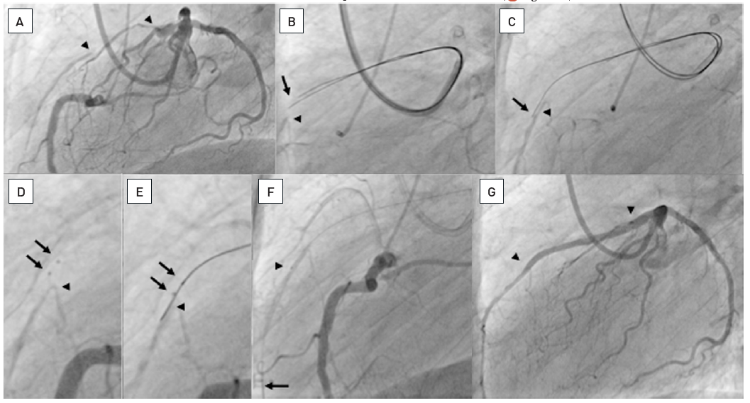
About 20mm long occlusion of the proximal LAD (between arrow heads, A). Sequence of panels in clockwise direction. A parallel wire approach using two Confianza Pro 9 wires did not lead to a distal entry, both wire tips (arrow) are above the distal target as visualized by contralateral injection (arrow head, B). One of the wires is advanced further (arrow) in parallel to the distal target (arrow head, C). Subsequently, after dilatation along the wire with a 1.25 and 2.0 mm balloon, the Stingray balloon catheter could be advanced. The two markers of the distal flat-shaped balloon are clearly visible (arrows) and positioned above the distal contrast filled target (arrow head, D). The the Stingray wire is advanced and directed to exit the catheter at that one of the two sideholes, which is directed downward towards the distal vessel. The wire exits the sidehole located between the markers (arrows) and reenters the distal lumen (arrow, E). After further advancement, the Stingray balloon catheter is exchanged using the trapping technique and a Finecross microcatheter advanced (arrow head), in order to then exchange the stiff Stingray wire for a soft floppy wire (arrow, F). Final result after two DES (arrow heads, G). Stenting was done under IVUS control (see Figure 36).
The idea to approach an occluded artery from the distal vessel segment originates from the initial experience of Geoff Hartzler who used a saphenous vein graft to open a native coronary artery from the reverse side. Large collateral connections are observed in some patients, and the ability to use these large arterioles as access was explored by Osamu Katoh . A wider application only became possible with refined tools such as soft tipped wires and microcatheters to be advanced through collateral channels. Initially, dilatation of the septal channel was shown to be a possible way to enlarge the access route safely, as these channels are surrounded by tissue, and injury may not lead to tamponade, which is a more imminent risk with epicardial channels.
The technique requires specific wire and balloon equipment, and should only be undertaken after training or instruction with an experienced operator. This complex method is applicable when it is deemed possible to pass a wire to the CTO from the collateral donor artery retrogradely towards the distal aspect of the vessel (e.g., a septal branch or an epicardial vessel). The steps involved include the passage of a soft polymer-coated wire via the retrograde collateral into the distal vessel which is then steered proximally to approach the distal cap of the occlusion retrogradely.
The retrograde system will be disengaged only at the end of the procedure if the wire is externalised. If an antegrade wire is advanced and the procedure is to be concluded via this course, the retrograde system should be retrieved as early as possible, but also as late as necessary. There may be situations, when the occlusion of the RCA includes the crux, and bifurcation stenting of the crux is required, having a “marker” in one of the distal branches from the retrograde approach may come in handy. In any instance, after retrieval of the retrograde system, a final injection should be done into the retrograde guiding catheter to ensure the integrity of the collateral pathway and the donor segment.
The review of cases with an unsuccessful antegrade approach suggests that suitable retrograde collaterals are present in more than 50% of cases but this percentage may be an underestimate if an assessment with supra-selective injection with a microcatheter of the most promising collaterals is performed, or if dedicated equipment offers safe instrumentation of very tortuous epicardial collaterals.
The first and most important step when considering the retrograde approach is the angiographic visualisation of the collateral pathways. There are more than 20 individual pathways described , but for the sake of the interventional approach, the basic division into septal and epicardial connections is sufficient. For a perfect visualisation it is important to avoid panning during the injection and filming, and to allow enough time for the contrast medium to reach the occluded segment.
Among the important features for the assessment of a possible suitable route for wire access to the distal occluded segment is the diameter of the collateral connections. This was initially graded in 3 categories of collateral connection size (CC) (CC0: no angiographic continuous connection; CC1: threadlike connection (<0.4mm); CC2: side branch like connection (>0.4mm)) (Figure 24). There are also occasional large connections especially via the apex of >1mm diameter which could be labelled CC3 connections. Other important features to consider are the tortuosity of the connection and the angle of take-off from the donor segment, as well as the site of entry into the receiving segment. A collateral connection should enter the receiving segment far enough away from the occlusion site to allow the alignment of the wire and support catheter within the distal segment for the retrograde penetration of the occlusion.
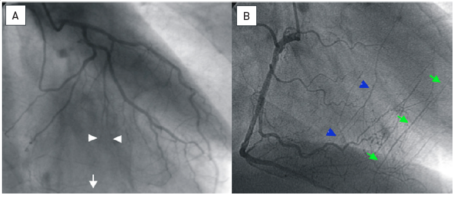
A. The collateral connection via septal branches from the LAD to branches of the PDA (white arrow) is not continuously visible and interrupted at the arrow heads: CC0. B. Patient with LAD occlusion and coexisting collateral connections from the PDA, some of thread-like size (blue arrow heads: CC1), some of them side branch size (green arrows: CC2) (modified from .)
A score integrating these important factors was suggested which, however, cannot account for the operator’s experience, which is the most important factor in determining whether a collateral can be used as a so called “interventional collateral” (REF McEnt).
The assessment also has to take into account that several collateral pathways may coexist, and that their appearance may change depending on the haemodynamic status of the collateral donor artery . Therefore, any previous angiograms should be carefully analysed. Disappearance of a collateral connection between two angiograms at different time points may not signify the actual closure of the collateral connection, but rather its dormant function. In some situations, a low pressure balloon occlusion of one of the pathways may be used to explore alternative routes, which are more likely for a wire passage. Careful wire probing may still achieve wire passage (Figure 25). If septal and epicardial collaterals coexist, the septal pathway should be preferred because it is dilatable channel for device passage, and it is often the shorter connection. A large apical connection between the LAD and posterior descending coronary artery (PDA) may look promising because of its size, but the additional length of this way around the apex may cause problems due to the limited length of available catheters, and by the fact that the push around the apex is limited. The selection of collaterals is also dependent on the available wire and support catheters, and there has been considerable development during the past few years which has changed the approach considerably. However, one should keep in mind, that perforation of an epicardial collateral will inevitably be more problematic to control than damage to an intraseptal collateral pathway.
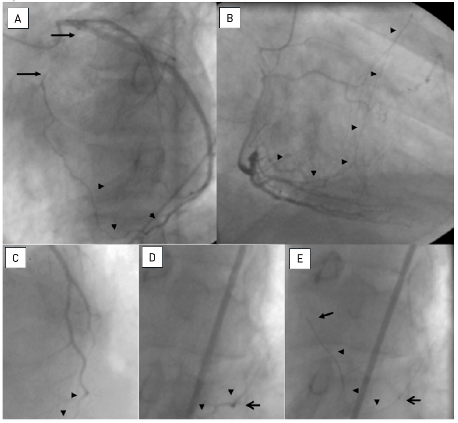
A: Proximal occlusion of the LAD (between arrows) collateralized via an epicardial connection from the distal LCX to a diagonal branch (arrowheads). B: Coexisting CC2 collaterals from the PDA to the LAD (arrow heads). The patient was brought back 4 months after the initial angiogram for PCI of the CTO. A retrograde approach was planned via the epicardial connection. At that time, however, the connection did no longer fill the diagonal (C, arrow heads) despite injection through a 8F guiding catheter. Advancement of a Finecross microcatheter (Terumo) (D, open arrow) and superselective injection through this catheter filled up the collateral only slightly better(arrow heads). E: Still, a Whisper LS wire (Abbott Vascular) could be gently advanced through the epicardial connection (arrow indicates wire tip, arrow heads wire course), and then later followed by the microcatheter (open arrow).
After identification of a possible collateral access to the distal collateral bed, the wire passage needs careful planning. The passage of the wire and the support catheters, or other devices like balloon catheters, requires considerable support by the guiding catheter to be advanced through the collateral channel. Therefore, a large catheter (7 Fr) is advantageous for the retrograde approach. If an ipsilateral collateral should be used for a retrograde approach e.g., an epicardial connection between LCX and diagonal branches or vice versa, an 8Fr size is preferable to allow for a wire passage around the collateral back into the guiding catheter. A shortened guiding catheter of 90cm length is preferable which is available from many vendors; otherwise, the catheter needs to be shortened on-site.
A general rule for the retrograde approach is that extreme caution is necessary to avoid any damage to the collateral donor vessels. Such a procedure may be long, and the position of a catheter through the left main and LAD through the septum for access to the RCA may impede perfusion by its shear diameter. Therefore, pre-existing lesions in the donor artery may require treatment before the retrograde access is attempted. Damage by the catheter tip directly, and thrombus formation must be avoided. Careful monitoring of the catheter tip position and frequent checking of the anticoagulatory effect of heparin by activated clotting time (ACT) are mandatory.
The wire used for passage through septal or epicardial collaterals needs to be soft-tipped and steerable and is usually supported by a microcatheter. Initially the choice of wire for collateral passage relied on already available non-dedicated wires such as the Whisper® ES (Abbott Vascular) and the Fielder FC (ASAHI Intecc).
Now dedicated wires for collateral passage are available and have replaced previous wires almost completely. They are the Sion family of wires (ASAHI Intecc) again based on the dual-core design. The tip strength is less than 1g, and they are non-tapered. The Sion is hydrophilic, whereas the Sion Black is additionally coated with PTFE. The Sion Blue on the other hand is hydrophobic and not as ideal for passing tiny tortuous collateral channel. These Sion wires have widened the possibility to approach even epicardial collaterals which previously were considered to delicate for a wire passage. For the tiniest of collaterals, the Fielder XTR can be tried, but the tip support is very low which may pose a problem once the wire needs to be followed with a microcatheter. Recently an additional wire was introduced with a very low tip load of 0.3 g specifically able to pass even the most tortuous segments with a low probability of collateral damage, the Suoh03 (ASAHI Intecc). This wire is a further addition of the wire arsenal for collateral passage.
Septal surfing or selective injection are two basic approaches to cross septal collaterals, typically from the LAD to the RCA. They are often the topic of dispute even though they should and can be used next to each other in daily practice. There are simple prerequisites which can decide the preferred approach depending on the collateral anatomy. A general use of septal surfing lead to perforation in 25% of all attempted collaterals, whereas an open mind takes all the options. If there is a large CC2 straight collateral connection, this will be passed straightforward with a Sion wire without the need for further confirmation, as a reference image will be sufficient to guide the advancement. If there is a high degree of tortuosity in a septal it is wise to inject contrast through collateral microcatheter after aspirating blood, to elucidate possible obstacles like branches and kinks in the collateral course. Then a Sion or Suoh03 can be used gently to overcome these obstacles, whereas surfing would have the risk of dissecting the collateral at these sensible way points. On the other hand, if we have not well-defined connections despite a septal branch that goes deep and typical into the septum, we may assume small, tiny connections that are often rather straight. Here septal surfing with a Sion Black provides often surprisingly easy and straight connections to the PDA by probing the possible routes without contrast guidance. The operator relies on his tactile feedback of low resistance in a connection as opposed to tight friction if the wire enters myocardium. The otherway round from the PDA to the LAD may be less likely to work with septal surfing, as the tortuous bended part of the septal collateral is closest to the PDA, and this needs to be overcome before then the wire enters the straighter segment towards the LAD. Therefore visualization of the entry point of the PDA collateral is often required. Surfing is not advised for epicardial connections, where we must have a precise idea of the collateral course, best obtained in multiple viewing angles.
A basic rule is the need for careful shaping of the wire tip, except for the Suoh03 which comes with a very small preshaped tip that should not be further altered. The shape of the Sion wires to be used within the should be a smallest possible short tip of 45 to 60°, but in retroflecting collateral bends even a 90° angle may be required. To make these tip changes possible, a microcatheter is mandatory. The preferred device for the collateral passage is the septal dilator catheter (Corsair or Corsair Pro; ASAHI Intecc), but occasionally also the FineCross MG (Terumo), can pass where the Corsair fails to cross, due to its sleek design (Figure 25). The range of microcatheters available for the retrograde approach has increased over the past years with additional devices from Vascular Solutions, the so-called Turnpike and Turnpike LP microcatheters.
Before the availability of these microcatheters active balloon dilatation of the septal channel was required to facilitate the catheter passage (Figure 26). This may still be necessary and requires small balloon diameters of 1.0 mm to 1.25 mm diameters. The rapid exchange (RX) type can be used as the hypo-tube part of the balloon catheter does not enter into the septal channel. Low pressure inflations of 3 to 4 atm are sufficient to dilate the channel and allow a catheter passage. If a distal dilatation within the occluded segment is required from the retrograde approach, where the balloon is further advanced, an OTW balloon should be preferred to avoid damage of the collaterals by the hypotube segment.
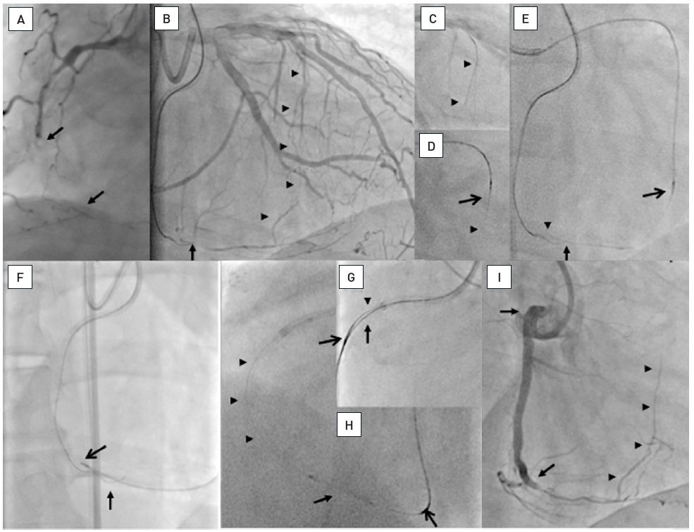
A: Long occlusion of the mid RCA (between arrows) and poor distal target vessel. B: An antegrade Confianza Pro 9 (ASAHI Intecc) is advanced until the crux where the tip is subintimal (arrow) through a 7F AL1 side hole 90 cm guiding catheter (Launcher, Medtronic). CC1 collaterals from the LAD to the PDA are visible (arrow heads), the LCA is engaged with a 7F EBU 4.0 side hole guiding catheter of 90 cm length (Launcher, Medtronic). C: A Fielder FC wire (ASAHA Intecc) is advanced (arrow heads). D: A Corsair catheter (ASAHI Intecc) (open arrow) follows the wire (arrow head). E: After passage of the wire into the PDA (arrow head) close to the antegrade wire tip (arrow), the Corsair is slowly advanced in rotating movements and dilates the septal channel (open arrow). F: It is then advanced into the PDA (open arrow) passed the antegrade wire (arrow), and the initial wire is exchanged to wires of increasing stiffness. G: Finally a Confianza Pro 9 (ASAHI Intecc) can be advanced along the antegrade wire (arrow) towards the RCA ostium followed by the advancement of the Corsair catheter (open arrow), and the retrograde wire is entered into the antegrade guiding catheter (arrow head). Not shown is the advancing of the Corsair catheter into the guiding catheter and exchange for a 300 cm Fielder XT wire (ASAHI Intecc), which is externalized out of the antegrade sheath. H: The Corsair catheter is then moved back into the PDA (open arrow) to protect the septal pathway, and a balloon catheter (Maverick RX, Boston Scientific) is advanced over the tip of the externalized wire. J: After stent placement of four DES (between arrows) over the externalized wire, the Corsair and retrograde wire are pulled out. The final angiogram shows the reverse filling of the septal channel that was dilated by the Corsair catheter without any damage (arrow heads).
The development of the Corsair catheter changed this approach considerably, as its soft narrow tip supported by a strong catheter shaft with metal support allows the gradual advancement and dilatation of the septal channel without the need for balloon predilatation. It is slowly “screwed” through the collateral channel and reaches the distal coronary bed of the occluded artery. It facilitates wire exchanges and, with more supportive wires, further advancement even into the occlusion itself. Unlike a regular microcatheter it will not move gradually backwards out of the collateral by the beating heart movement, which inevitably occurs with unsupported wires. The Corsair microcatheter has received some developmental iterations, the latest is the Corsair XS ® (ASAHI Intecc) which has a lower profile then the original Corsair, and it is similar to the Turnpike LP (Vascular Solutions) which has advantages in small diameter collaterals.
The use of the Corsair septal dilator also may facilitate device passage through epicardial channels, though these channels require specific care in order to avoid overstretching and damage. Especially those channels on the epicardial surface from the diagonal to the marginal branches and vice versa may be better passed with the Finecross, as this catheter enforces less strain upon the collateral channel. The problem of the epicardial catheter passage has been improved by the introduction of the much softer and sleeker Caravel microcatheter (ASAHI Intecc) which should be now the preferred microcatheter in these settings.
The patient may experience chest pain during the retrograde procedure and this technique needs careful attention to the potential causes of this ischaemia. If possible, the largest and most important collateral connection should not be used for retrograde access, but rather a smaller (and often less tortuous) connection in order not to impair perfusion to the occluded territory for the duration of the procedure. Furthermore, there is the risk of spasm or dissection in the donor artery if there are pre-existing lesions. If no major obstruction is detected, the procedure may be continued despite the discomfort of the patient, and analgesia should be applied.
An important rule to avoid perforations related to the collateral passage is to advance forcing the microcatheter to follow a wire that had passed the collateral. We may use some force to follow the course of the vessel, especially in septal collaterals, but we must be aware that the main trauma to the collateral will be rather induced by the microcatheter attempt then by the wire. One should desist from forcing the microcatheter across extreme bends especially in epicardials, where even now epicardial on the surface of the heart can be crossed. If the microcatheter cannot follow we should still seize the opportunity to use the distal wire as a marker wire, as this original method of the retrograde technique still works (see below).
The marker-wire or kissing-wire approach can be used to facilitate the antegrade wire direction. It may be a good way to become familiar with the retrograde wire passage without applying the complex procedural extension described below. One major advantage of placing a marker wire in the distal occlusion cap is that no additional contrast injection is needed during the manipulation of the antegrade wire. The distal marker serves as an ideal target to direct the antegrade wire (Figure 27). In patients with severely impaired renal function with a low limit of contrast allowance, such an approach may help to keep contrast use as low as possible.
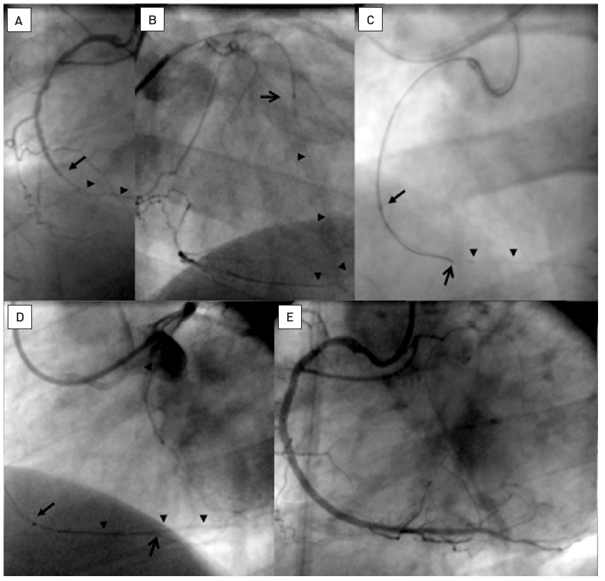
Occlusion of the RCA (A: arrow) with a long bridging collateral making the definition of the proximal entry point difficult. Therefore a retrograde approach was chosen via a first septal branch of the LAD. B: A Finecross microcatheter (Terumo) is advanced and a Whisper LS wire (Abbott Vascular) passed through the collateral connection into the PDA (arrow heads). The microcatheter could not be advanced further. C: The retrograde wire could be advanced into the occlusion towards the proximal entry. From antegrade a Miracle 3G wire (ASAHI Intecc) is advanced over a Finecross (arrow) along the retrograde wire as a marker further distally (open arrow). D: Finally the antegrade wire passed the occlusion into the distal segment, and the antegrade microcatheter is further advanced (arrow). E: Final result after 2 DES.
In situations where the microcatheter cannot follow the collateral wire, for example in very tortuous epicardial collaterals, the marker wire approach may be the only way to overcome the occlusion and should not be forgotten as a valuable technical option.
The ideal course of a retrograde approach would be the retrograde wire crossing from the distal true lumen into the true lumen proximal of the occlusion. The direct penetration of the distal fibrous cap may be easier than the penetration of the more resistant proximal cap. The ideal platform to attempt this will be the positioning of a support catheter (Corsair, Caravel, Turnpike) in the segment close to the distal cap. Then the wire selection can be similar to that of the antegrade approach, although one must consider the translational movement of the heart which may cause considerable instability of the microcatheter tip. In these conditions, a “heavier” wire like an Ultimate may be better controllable for the retrograde passage. Occasionally stronger support is required, but if this does not lead to advancement within the lumen, entry of a dissection plane is likely which then requires a change of strategy. A valuable addition for retrograde direct wiring are the Gaia family of wires. One could start with a soft Gaia 1, however, in most instances the length of the passage from the guide catheter through the microcatheter to the distal cap makes a rather strong wire preferable such as the Gaia 3.
If a true lumen wire passage is achieved, the next step is to dilate the occlusion. Theoretically this could be achieved by advancing an OTW balloon retrogradely to create a small lumen, but the push support is very limited; it can be increased once the retrograde wire is trapped within the antegrade guiding catheter. The retrograde support catheter can then advance retrogradely through the occlusion and thus create a small lumen for the passage of the antegrade wire. In most cases an externalisation of a RG3 wire will follow which then provides excellent support and also guide catheter control. If this retrograde passage is not possible, an attempt can be made to advance a recanalization wire antegradely alongside the retrograde wire. The use of support catheters, however, is to be preferred as the most successful mode. If externalisation of the retrograde wire is not planned for some reason, one could also advance the support catheter into the antegrade guiding catheter, then remove the retrograde wire, and attempt to direct an antegrade wire into the distal orifice of the retrograde support catheter, thus facilitating antegrade wire passage (rendezvous or tip-in technique) .
When the antegrade or retrograde wire enters a false lumen, a CART-technique can be used . The basic principle of the technique will be described, but for further and detailed study one should refer to the various case reports published on this topic , , , , , , , , ], and recent more detailed overviews , . The technique is still developing as evident from the fact that the original CART technique is now less frequently applied than the reverse CART technique , .
The basic principle is Dr Katoh’s concept of creating a connection between a wire located in a dissection plane, with the true lumen distal (CART) or proximal (reverse CART) of the occlusion (Figure 28). This technique requires both an antegrade and retrograde wire positioned within the occlusion; one wire is advanced to meet the other wire but fails to achieve position within the same plane. The wires need to be parallel within the occlusion at some point, then a balloon is advanced to dilate at the site where one of the wires is presumably entering into a dissection. This balloon can be advanced via the collateral (CART) (Figure 29) or from the antegrade side (reverse CART) (Figure 30), and needs to dilate within the occlusion. This may require a gradual increase of balloon size to allow its passage, as for the successful wire re-entry into the true lumen; the inflated balloon diameter needs to be big enough to create a dissection. To assess the optimum balloon diameter, intravascular ultrasound (IVUS) may be used for imaging. IVUS is preferred over repeated contrast injections as the latter may create an unnecessary extension of the intended dissection, and provides an inferior assessment of the true vessel size as compared to the ultrasound approach.
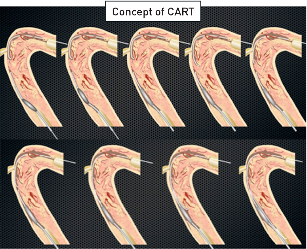
The concept of CART as described by Dr. Osamu Katoh. An occlusion is approached with wires from antegrade and retrograde. Both wires are in a subintimal position. Over the retrograde wire, a balloon is advanced and inflated within the subintimal space to create a connection between proximal and distal subintimal space. This facilitates the entry of the antegrade wire into the distal lumen along the retrograde balloon. For the reverse CART approach, the retrograde wire is advanced into a subintimal connection created by an antegrade balloon (adapted from Dr Katoh’s "Retrograde for CTO Course" presented at the CCT 2008, Kobe, Japan).
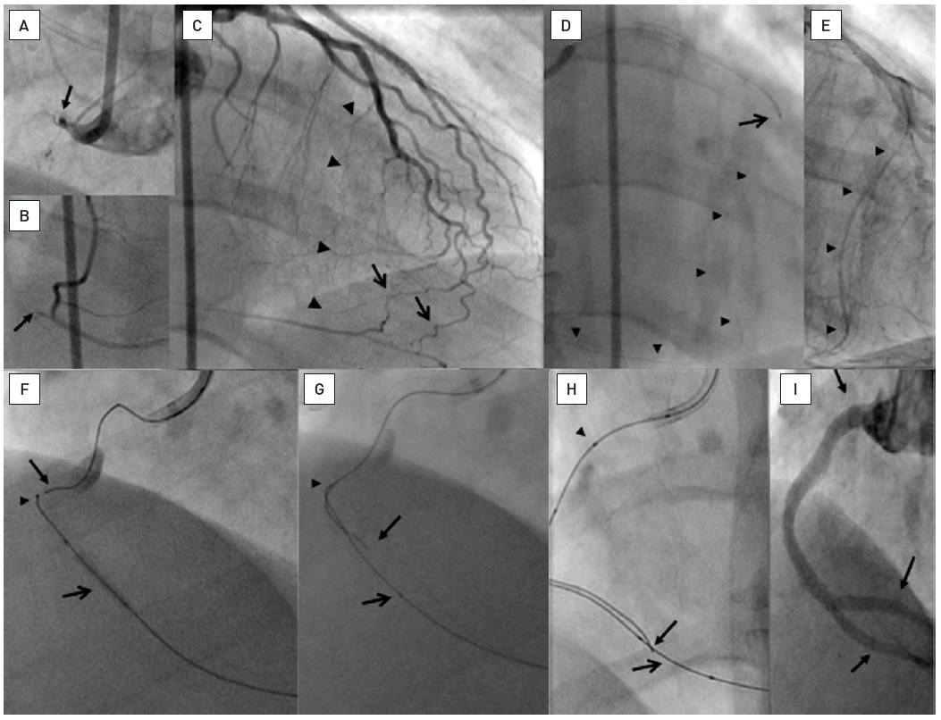
In clockwise sequence A: Proximal occlusion of the RCA (arrow) extending until the crux cordis (B, arrow). C: The LAD supplies epicardial (arrow) and septal collateral pathways to the PDA (arrow heads). D: The septal passage is chosen, and a 300 cm Whisper LS wire (Abbott Vascular) (arrow heads) passed through into the PDA. The wire is supported by a Transit microcatheter (Cordis) which cannot pass the collaterals. E: The septal collaterals are dilated with a 1.25 mm balloon (Ryujin Plus, Terumo) providing an access (arrow heads) for an OTW balloon (2.5 mm Avion Plus (Invatec)) to the PDA. F: A Miracle 3G (ASAHI Intecc) is then exchanged over the inflated balloon to provide stability retrogradely (arrow head), and another Miracle 3G is advanced antegradely towards the retrograde wire (arrow). Proximal contrast stain indicates a dissection. G: The antegrade wire (arrow) can negotiate an angle in the mid RCA and is steered towards the balloon that is frequently inflated to create a connection to the proximal dissection plane. The retrograde wire tip is indicated by the arrow head. H: Finally the antegrade wire (arrow) is passed along the balloon (open arrow) into the PDA. The antegrade wire is supported by a QuickCross microcatheter (Spectranetics) with three markers (arrow head). J: The vessel is reconstructed including the distal bifurcation with five DES (between arrows).
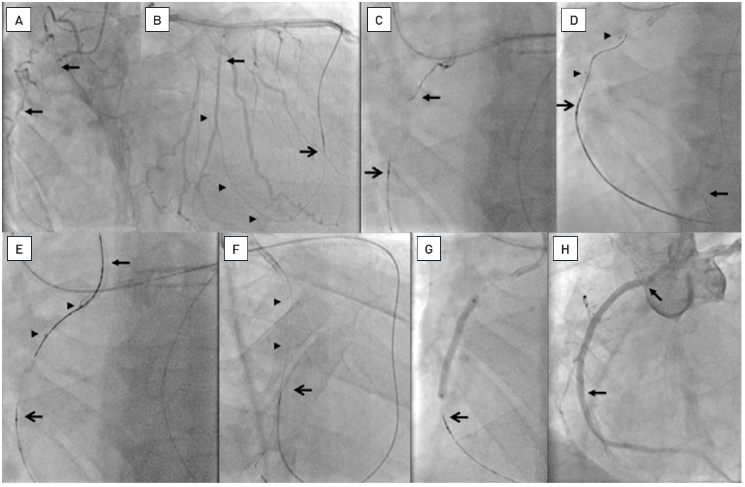
A. Occlusion of the RCA (between arrows). B. Passage of a septal collateral with a Whisper LS wire (Abbott Vascular) supported by a Corsair catheter (open arrow, ASAHI Intecc). The wire is advanced from a right ventricular side branch (arrow heads) into the segment distal to the occlusion (arrow). C. A wire (arrow; ASAHI Intecc) is advanced from the antegrade guiding catheter towards the Corsair catheter (open arrow). D. The antegrade wire is advanced distally in a side branch (arrow), and a balloon catheter (between arrow heads) advanced and inflated. Along this balloon a Miracle 3G wire (ASAHI Intecc) is advanced retrogradely. E. Finally this wire is directed into the guiding catheter (arrow). F. After advancing the Corsair catheter into the guiding catheter and exchanging the Miracle wire for a 300 cm Fielder XT (ASAHI Intecc) this wire is externalized (arrow heads) and the Corsair moved back (open arrow). G. The Corsair is further moved back (open arrow) and then ballon dilatation and stenting could be performed over the externalized wire. H. Two Everolimus-eluting stents (Xience V, Abbott Vascular) are implanted up to the ostium, which could be well controlled by retrieving the guiding catheter supported by the externalized wire.
For a typical reverse CART approach the balloon remains partly inflated during the retrograde attempt to pass the wire along the balloon into the proximal true lumen. If this is not achieved, placement of an IVUS catheter helps to locate the position of the distal wire and to direct it into the proximal true lumen. Which wire to use depends on the morphology of the occlusion, such as the calcium content and resistance to the wire. Several wires may be attempted, such as a soft PTFE with a looped wire, which is termed knuckle wire passage, or a Ultimate or the stiffer Confianza Pro wire. Torque control and penetration force is the reason for a specific wire selection and must be adapted to the individual situation. In calcific lesions a Pilot 200 wire may be of help, preferably without resorting to the knuckling, but in case of failed passage, knuckling may help.
The knuckle wire approach increases the rate and extent of subintimal dissection as compared to the classical wire based reverse CART procedure. In the latter approach a subintimal pathway was actually found only in about 25% of the retrograde cases in a Japanese study . The extent of subintimal passage may be much higher when the retrograde dissection approach, popular in the US and UK, is applied, as demonstrated in a recent IVUS study with upto 90% of subintimal passage with the retrograde technique. This approach uses the retrograden and antegrade knuckle wire (preferably a Fielder XT or Pilot 200 wire) more extensively and increases thus the extent of subintimal pathways. There lies also a misinterpretation of technical sdetails of the retrograde approach within the so-called hybrid approach. In this algorithm the retrograde technique is termed retrograde dissection re-entry, and set synonymous with reverse CART, whereas the reverse CART technique on the contrary tries to stay within the plaque. In fact, the most important concept of the CART technique is not to create a subintimal dissection, but to create space within the body of the occlusion. The crossing of the wire from the distal true lumen to the proximal true lumen should happen within the occlusive plaque, and therefore it is mandatory to advance the antegrade wire far enough distal to allow the antegrade balloon passage into this are for creating the space for re-entry . A frequent mistake is, that the retrograde wire is passed beyond the proximal cap into the subintimal space, and the exit from this space into the true lumen in a vessel segment with only little plaque may be near to impossible. In such a situation, the point of re-entry must be moved further distal into the body of the occlusion. If this is achieved, the rate of subintimal stent placement will be low.
A recent expert group tried to define the evolving concepts of the reverse CART technique with new more precise terms. We may speak of the conventional reverse CART technique with a larger balloon being the target when a retrograde wire was advanced far into the CTO body. On the other hand we have the directed reverse CRT, where the concept is to advance a wire antegradely as far as possible, advance a rather small balloon of 2 to 2.5mm, and use this as a target from retrograde. This concept works best with the new wires of the Gaia type, which provide excellent torque control. Finally a third type would be the extended reverse CART technique, when the operator fails to penetrate the proximal cap, but can advance the retrograde wire far proximal, and then the connection is done close to but proximal of the proximal cap. Figure 31 shows the main features of these basic types.
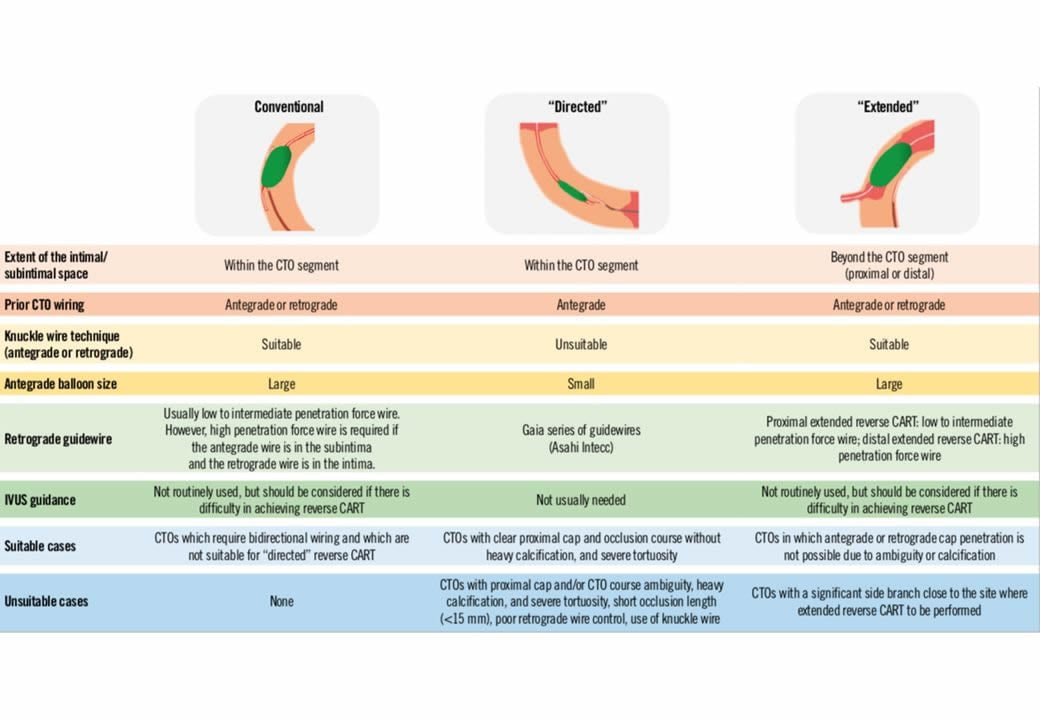
Overview of the three subtypes of the reverse CART technique. The essential elements of each technique are described in terms of extent of the intimal/subintimal space, prior CTO wiring, use of knuckle wire technique, antegrade balloon size, necessity of IVUS guidance, suitable and unsuitable cases. (from).
As mentioned above, this approach is favoured in some countries as part of the hybrid algorithm . The idea behind this use of a knuckle wire technique to connect the antegrade and retrograde wires is that it may be quicker than a wire based careful probing towards an antegrade or retrograde wire target. Whether this idea holds true is yet to be tested. However, it is important to know also this kind of approach, as it may be the only safe way to explore long occlusions typically of the right coronary artery, where the course of the vessel may remain unclear, and often tortuous. The advantage of a knuckled wire like the Fielder XT is, that it is unlikely to penetrate the adventitia and rather follows the course of the main vessel. Likewise, many calcified lesions will be overcome only by going around the calcium with this knuckle wire approach.
Once the retrograde wire is passed into the true proximal vessel lumen, the next step is to facilitate balloon passage. Several methods have been described above, however, the most straightforward technique that yields the best support for balloon and stent advancement is externalisation of the wire, i.e., passage of the retrograde wire into the antegrade guiding catheter and further out of the catheter through the Y-connector. To make this possible, first of all the wire length is a limitation that needs to be accommodated for by careful initial planning, then the collaterals need to be protected from the stiffer part of the wire, and the retrograde guiding catheter position needs to be controlled at all times to avoid it being sucked into the artery and causing damage.
The advantage of an externalised wire is especially valuable in cases of ostial or very proximal occlusions of the RCA where the guiding catheter needs to be pushed out of the ostium for optimal stent placement. If the guiding catheter is controlled on an externalised wire, its` position cannot be lost as would be the case if it depended on an antegrade wire only (Figure 32).
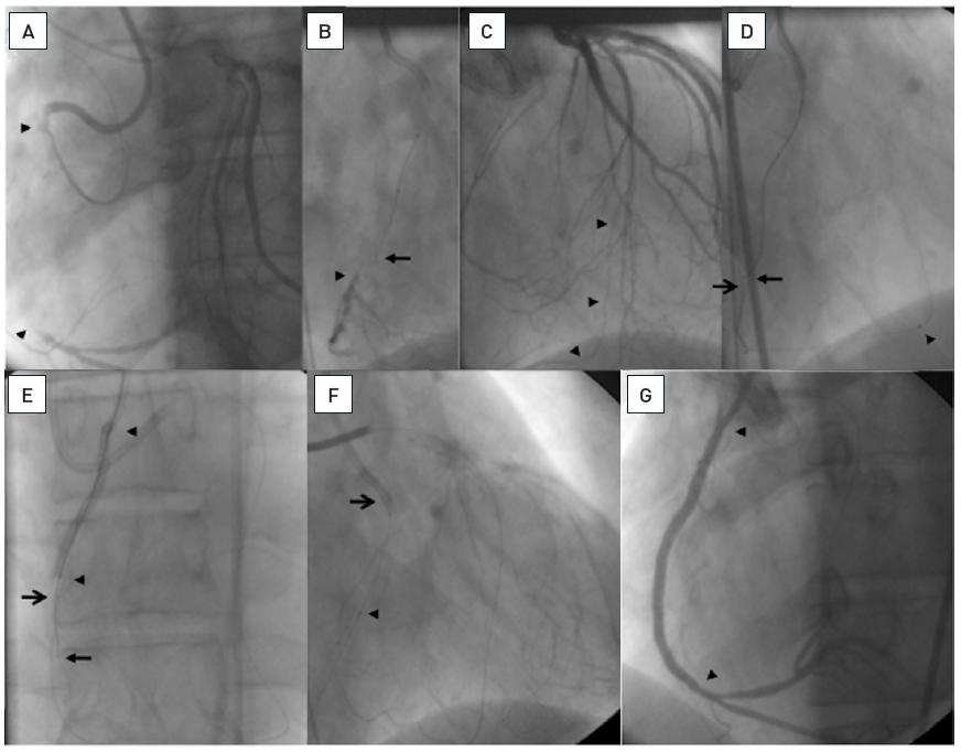
A very long occlusion of the RCA from proximal to close to the crux cordis (arrow heads, A). After several attempts to advance an antegrade wire (arrow) towards the distal lumen (arrow head) the wire is deviating from the true vessel course (B). In the presence of well developed CC2 collaterals from the LAD to the PDA (arrow heads, C), the decision was made to switch to a retrograde approach after 20 minutes of fluouro time. A 300 cm Whisper LS wire (Abbott Vascular) is advanced to the PDA (open arrow) and then towards the antegrade marker wire (arrow) supported and followed by a Finecross microcatheter (arrow head, D). To facilitate the progress of the retrograde wire (open arrow) towards the proximal lumen, a reverse CART technique is applied with inflating a long 2.5mm balloon (arrow heads) over the antegrade wire (arrow, E). This enabled the entry of the retrograde wire into the antegrade guiding catheter (open arrow, F) and the externalization of this wire. The microcatheter (arrow head) is left in place to protect the collateral during the wire externalization. Balloon inflation and placement of three DES (arrow heads, G) are completed using the externalized wire.
One precaution which helps to make this technique possible is the use of short guiding catheters preferably both for the antegrade and retrograde access (e.g., available at 90 cm length as Launcher®, Medtronic, Minneapolis, MN, USA). In addition, the externalised wire needs to be a wire of 300cm length or longer with moderate stiffness in the shaft to make the push out possible. In general, the previously used long Fielder FC and XT wires (ASAHI Intecc) are completely replaced by the 330 cm long dedicated externalisation wire (ASAHI Intecc). But even with this extra length in long collateral pathways, especially via the apex, and in tall patients where a 90cm guide is not possible, the externalisation process may become difficult. A trick is to use guide catheter extensions (Guideliner™, Guidezilla™, Guidion™) to allow the entry into the antegrade guide catheter deeper within the vessel, and the trapping technique is then applied within this guide extension.
If the wire can be advanced retrogradely into the guiding catheter lumen it can be trapped there, and the retrograde support catheter pushed into the guiding catheter. From there, the guidewire can be exchanged for a 300 cm or longer soft wire, which is then pushed out from the other side of the catheter. Any balloon or stent can then be advanced reversely over this wire. Before the devices can be advanced, the retrograde support catheter needs to be moved back from the guiding catheter to make room for the antegrade devices. It needs to be moved back distal to the segment where the most distal stent will be placed, but it needs to be kept across the full course of the collateral pathway to protect it from the stiff part of the externalised wire. This move back procedure for disengaging the support catheter may often take some time, especially if it is a Corsair or Turnpike catheter. It can be achieved by gradual pull while turning the microcatheter. A FineCross™ catheter will be easier to retrieve on the one hand, but it needs more care not to pull it back too far as it does not keep its position as stable as a Corsair. The Caravel catheter has features between Finecross and Caravel, it should not be turned like a Corsair, as the tip is more fragile, but it provides a more stable position than the Finecross. During this pullback manoeuvre, the tip of the retrograde guiding catheter must be kept out of the coronary orifice to avoid deep and forceful engagement. There is no problem in keeping the guiding catheter far out in the aorta as the support is maintained by the Corsair catheter.
In ostial occlusions especially of the RCA, intubation of the coronary artery from the antegrade approach may be difficult and not always in alignment with the vessel course which makes the retrograde access into the catheter lumen difficult. In these instances, the wire can be advanced into the aortic root and caught by a snare through the antegrade guiding catheter. One popular and easy to use snares is the ENSnare (Merit Medical, South Jordan UT, US). The snaring of the wire can be made easier when the wire and the snare are advanced into the right brachiocephalic artery, as there the space for the wire to escape the snare is reduced. There is one caution for the snaring approach. When a stiff wire is snared, this wire cannot be exchanged. But it can be used as a purchase to advance then the microcatheter into the aortic root. As the next step, the stiff wire needs to be released from the catheter that holds the snare, again. Subsequently a soft wire, typically the 330cm or longer externalization wire is then advanced and then again snared to be pulled through and out of the antegrade guide catheter. The snared tip of the externalization wire must be cut with a scissor and then balloons and stents advanced from the antegrade side.
There are instances where the retrograde wire can be advanced into the antegrade wire, but the microcatheter cannot follow through a calcified or otherwise non-dilatable lesion despite trapping the wire in the guide catheter. There is the option to force the microcatheter under utmost tension, but this could not only endanger the collateral pthway but also destroy the tip of the microcatheter, especially when a softer tip catheter is used like the Caravel. An initial option is to exchange for a different microcatheter advanced from retrograde while the tip od the retrograde wire is still trapped, always requiring an extension wire attached to the retrograde wire. The alternative is to perform a tip-in manoeuver .
The tip-in manoeuver can be done in the distal part of the guide catheter or even more rapid when a guide extension is used for the retrograde wire passage. Ideally the tip of the retrograde wire must not be destroyed ansd should be in a straight shape with a small angle to allow the manoeuvring within the guide. From antegrade a microcatheter is advanced proximal to the retrograde wire. The best chance to enable the wire to enter into the microcatheter tip is on a curvature, so the wire will be advanced where the guide passes across the aortic arch. It is surprisingly easy to achieve this tip-in. However, the microcatheter to be advanced now along the retrograde wire needs to provide a physical force that allows the passage through the tight part of the lesion. While any microcatheter can be tried, the Turnpike Spiral® (Vascular Solutions) appears to be a very good choice as the screw like outer surface structure of this microcatheter tip helps advancing the device across the lesion particularly well.
After the guidewire has been successfully advanced across the occlusion, and most importantly, its correct intravascular position checked on at least two orthogonal views with a contralateral injection, a balloon needs to be advanced. This is achieved with low-profile1 mm to 1.25 mm balloons, which are then followed by an adequately sized balloon. Several suppliers provide dedicated balloons and operators need to become familiar with these (e.g., MiniTrek™ (Abbott Vascular), Tazuna® or Ryurei ® (Terumo), Sprinter Legend® (Medtronic), Falcon CTO (Invatec), Sapphire Pro II® and Spphire Pro III® (Orbus-Neich)) (Table 3). It needs to be mentioned that the diameter on the balloon labels of these speciality balloons is not related to device success, as the shape of the tip, the transition from tip to balloon, and the backup provided by the hypotube shaft will determine balloon passage, not a small nominal balloon diameter. With modern day low-profile balloons, there is no advantage regarding balloon passage for an OTW-balloon over a rapid-exchange monorail catheter system, rather the improved hypotube shaft of a rapid-exchange monorail catheter will transmit the applied pushing force better than the combination of the guidewire and the OTW tube.
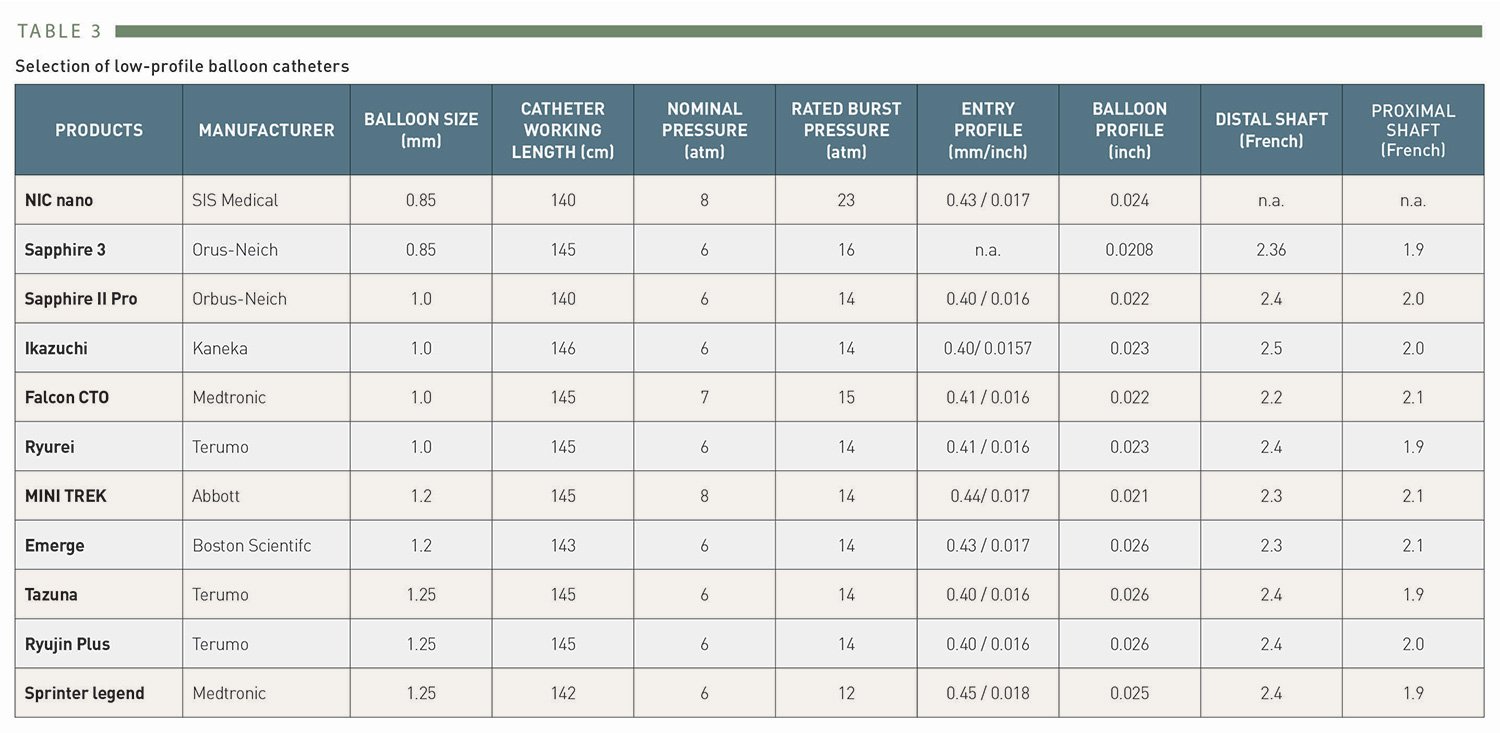
Selection of low-profile balloon catheters
Resistance to balloon advancement results in a backing out of the guide catheter from the ostium of the coronary artery. If even a small balloon cannot be advanced, there are several techniques available to increase support which are described above (guide catheter selection).
In some instances with heavily calcified lesions a rotablator is required. However, it may be extremely difficult to exchange the recanalization wire for the delicate 0.010" rotablator guidewire which is extremely difficult to manipulate in complex coronary lesions. Wire exchange is made possible by advancing a microcatheter as far as possible into the occlusion in a wedge position, then removing the recanalization wire and advancing the RotaWire gently. Once achieved, a small rotablator burr may then be advanced. Another specific device useful in this situation would be the Excimer® laser catheter (Spectranetics Inc., Colorado Springs, CO, USA), but due to high hardware costs and limited applications these devices are rarely found in coronary catheterisation labs today. , . A new device which may help to prepare the lesion for balloon passage through the occlusion is the Tornus support catheter (ASAHI Intecc), which can be advanced over the guidewire across the occlusion in an anti-clockwise screwing movement (Figure 33). If there is no evidence of severe calcification, the Corsair catheter (ASAHI Intecc) , originally developed for the retrograde approach, can be used as an antegrade support catheter and may achieve lesion passage in balloon-resistant lesions.
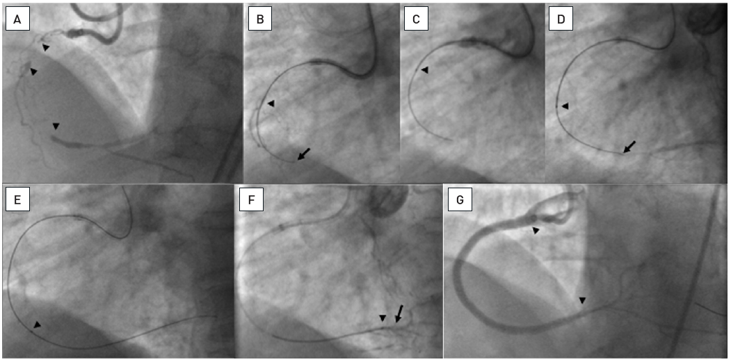
Complex diffusely diseased RCA with one occlusion proximal (arrow heads) and a further occlusion distal before the crux cordis (arrow head, A). A Miracle 3G wire could be advanced through the occluded proximal segment (arrow), as visualized by contrast filling of the middle segment (arrow head, B). However, no balloon could be advanced. Thus, a Tornus catheter was used and successfully passed into the proximal segment (arrow head, C). With further wire advancement (arrow) the Tornus followed into the middle segment (arrow head, D). Finally the wire crossed into the distal posterolateral branch and the Tornus was further advanced (arrow head, E). After crossing the occlusion (arrow head) a soft floppy wire was exchanged over the Tornus catheter (arrow, F). Balloon dilatation was facilitated by the crossing of the Tornus, and four DES were implanted (arrowheads, G).
In calcified lesions when the balloon does not appear to inflate fully, as in non-occlusive lesions, a preparation of the lesuion is advised to avoid subsequent stent underexpansion. One approach described above Is the rotablator. Additional devices are now coming to Europe such as the orbital atherectomy and the intravascular lithoplasty . Both options can be alternatively applied to enable full balloon expansion and then the stent deployment.
After the initial balloon passage with a small balloon, the selection of the proper size of balloon for subsequent full lesion dilatation may be difficult, this also holds true for the selection of the proper stent size. Therefore, intra-coronary nitroglycerine is given to increase the distal vessel size which is always constricted after the recanalization. As with the collateral supply, the existing pressure had been in the range of 30 mmHg to 40 mmHg, and the vasodilatory response to the increased antegrade pressure takes time and may lead to underestimation of actual distal vessel diameters. The balloon length is chosen to facilitate the subsequent stent advancement. Stent implantation is mandatory in CTOs though there may be rare exceptions in very small vessels and short occlusions, where a stent is not implanted. However, the question arises as to the functional relevance of these CTOs in secondary small coronary arteries.
There is a clear indication to use DES in CTOs to ensure a high long-term patency which has been proven by numerous registry studies , , , , , , , , and finally also by randomised trials , , (Figure 34A and Figure 34B). A specific problem of balloon angioplasty and later BMS implantation was the high reocclusion rate , . This difficulty seems to have been almost overcome by the use of DES (Figure 35A and Figure 35B). and recent amendments to guidelines have given a clear indication for their use . The need for long and multiple stents no longer appears to have a considerable impact on vessel patency, although very late stent thrombosis in this specific lesion subset maybe more frequent than with BMS, at least with the first generation DES used in the initial studies . After balloon dilatation of a CTO, it may be advantageous to employ a liberal stent coverage with maximised stent expansion in order to avoid focal restenosis at the edges of the stent(s) when they are implanted within severely atherosclerotic segments, and to reduce flow turbulence to reduce the risk of stent thrombosis. There is no strong evidence for this advice, and support by prospective studies is needed.
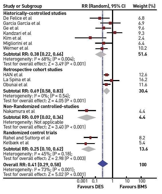
Influence of the use of DES versus BMS on the incidence of MACE [from ]
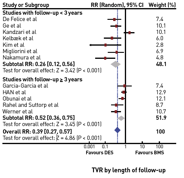
Persistent improvement of TVR when using DES as compared to BMS in both short-term and long-term follow-up studies and registries [from ]
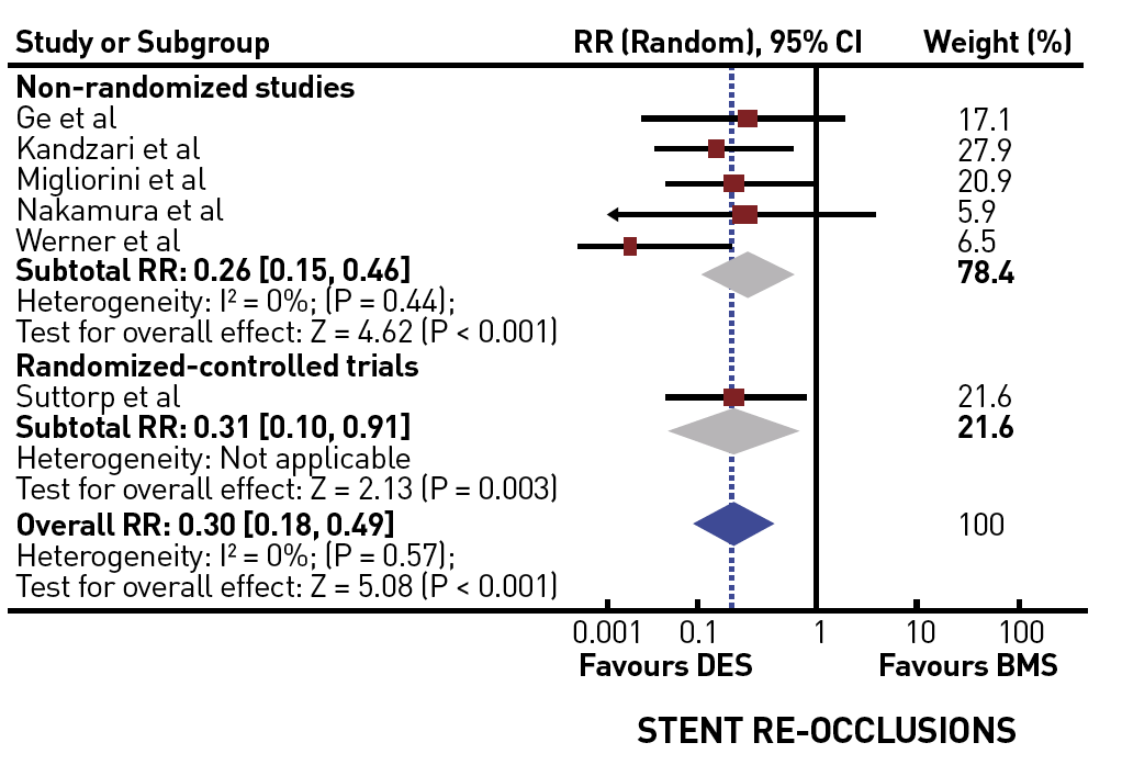
Significantly reduced incidence of stent reocclusion with the use of DES [from ]
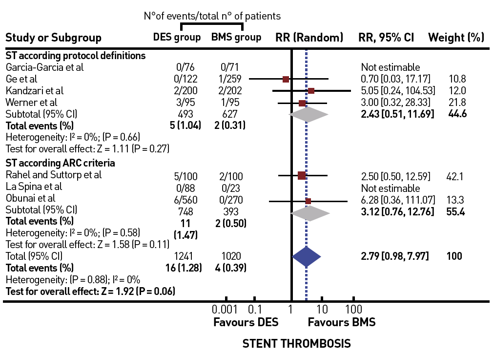
Trend for an increased risk of stent thrombosis in CTOs treated by DES versus BMS [from ]
The disadvantage of extensive stent placement is the continued loss of vessel conformity by this so-called “full metal jacket”. This may lead to stent fractures and increased rate of restenosis or even reocclusions. This phenomenon is reported with first generation DES , , but probably not uncommon with more recent DES. It might be less detected because of the thinner stent struts with lower radiopacity (Figure 36).
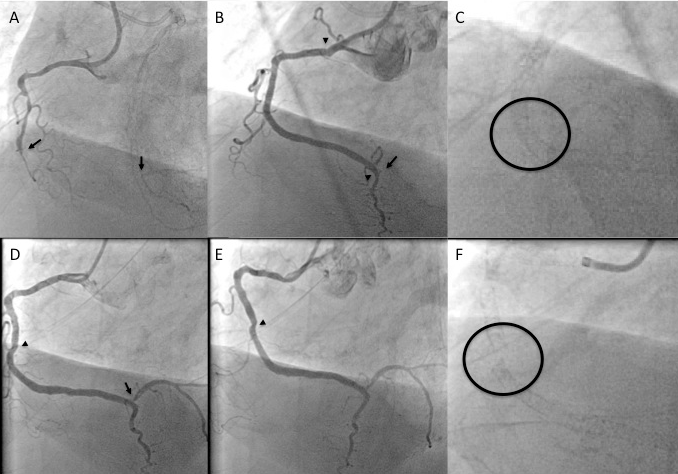
A. Long occlusion of the distal RCA (between arrows). B. After retrograde reverse CART approach 3 Xience stents are implanted (between arrowheads). The PL branch is occluded after stenting (arrow). C. Magnified image of the implanted stents at the site of pronounced vessel motion. D and E. At 3 month follow-up in order to check for the PL branch, the PL branch is found patent, but at the angulation of the mid RCA segment, the lumen appears to be obstructed during systole (E). F. The magnified image shows a clear gap within the stent as evidence of stent fracture. This was later covered by an additional stent.
The future development will tend towards the use of fully bioresorbable vascular scaffolds in CTOs, but the current experience is limited to less complex CTOs, and experienced a setback with the removal of the first generation BRS from the market. However, in small intial studies the concept of BRS in CTOs provided some encouraging results , , , , . Despite the withdrawal from the market we should expect a revival in the future with newer generations of BRS especially for younger patients with little or no calcifications (Figure 37).
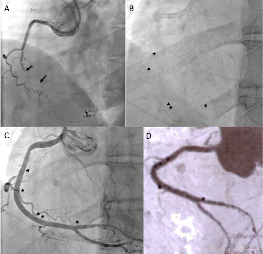
A. Distal short RCA occlusion (between arrows) with additional long diffuse distal RCA segment in a 45 year old patient. B and C. After antegrade recanalisation 3 bioresorbable vascular scaffolds are implanted, the arrowheads indicate the platinum markers of the 3 stents. D. After 10 month a multislice CT shows a patent fully recovered artery with the platinum markers as bright black spots.
Intravascular ultrasound (IVUS) can be of use during several steps of the interventional process. As an advanced adjunctive technique requiring considerable expertise and experience, it may be used to locate the entry into an occlusion if a side branch takes off right at the proximal cap , , and the IVUS can be positioned at the take-off of this side branch (Figure 36). If the guidewire is advanced into the subintimal space, an IVUS catheter advanced into this false space may help facilitate re-entry into the true lumen , again a technique only for the experienced.
Where IVUS may be of general advantage is the assessment of stent placement and optimised stent expansion , . Full lesion coverage and expansion may be key factors to obtain persistent long-term success in these lesions. Especially in situations where a subintimal passage of the wire is present with distal re-entry, the location of the subintimal passage is important in order to find the right location for stent placement to ensure full coverage of the subintimal wire course (Figure 39). A further potential impact on facilitating successful wire passage could be brought about by the introduction of a forward-looking IVUS, which might help to select the proper entry point for penetration of the proximal occlusion cap (View related chapter: Intravascular ultrasound).
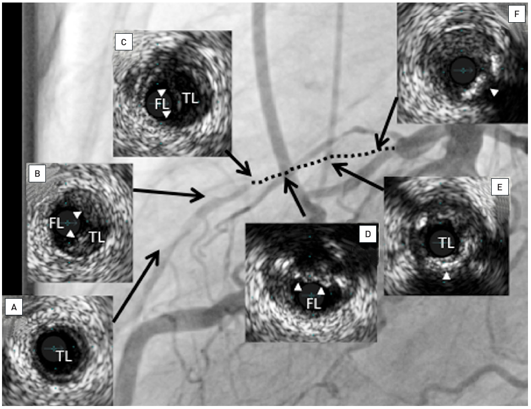
Occlusion of the LAD as shown in Figure 18. After using a re-entry device intravascular ultrasound was used to define the position of the stents to cover the subintimal wire passage and the occlusion. The inserts show the IVUS frames at the position as indicated by the arrows, TL indicates the true lumen, FL indicates false lumen position: Distal to the wire reentry (a); at the position of the wire reentry with plaque (arrow heads, b); subintimal wire passage in the false lumen (c); position where wire left the true lumen at the site of partly calcified plaque (arrow heads, d); occluded segment proximal to the wire exit with calcified plaque (arrow head, e); proximal at the site of the occlusion with soft occluding tissue and calcified plaque (arrow head, f). Two stents were placed from position to a site proximal to the occluded segment at position f as shown in Figure 21.
It would be ideal to have a clear roadmap of the vessel course of an occluded artery. Especially in a long-occluded RCA which often has a tortuous course, angiography fails to give an idea of the true vessel course, except when spots of calcium are present within the presumed vessel course. Furthermore, it would be helpful to identify problem zones within a calcified occlusion where the wire may be deviated into the subintimal space by dense calcium. Multislice computed tomography (MSCT) of a coronary artery with high-resolution acquisition systems may be helpful in these situations; preliminary experience is limited but is gaining interest. Initially the presence of calcium was confirmed as the main cause of procedural failure , , . The differentiation between occlusive calcified plaque as opposed to calcium within the vessel wall may help select patients who may still have a good chance for wire passage.
Unlike peripheral artery disease where the concept of roadmaps is easily applicable even within the angiography system, the heart is moving both with the heartbeat and with respiration. Therefore, a perfect overlay will not be possible in the near future. However, the idea of an overlay of a roadmap created by MSCT may help to assess the presumed wire course and improve the procedural success (Figure 40). Initial steps towards this goal are being attempted by industry and research groups , .
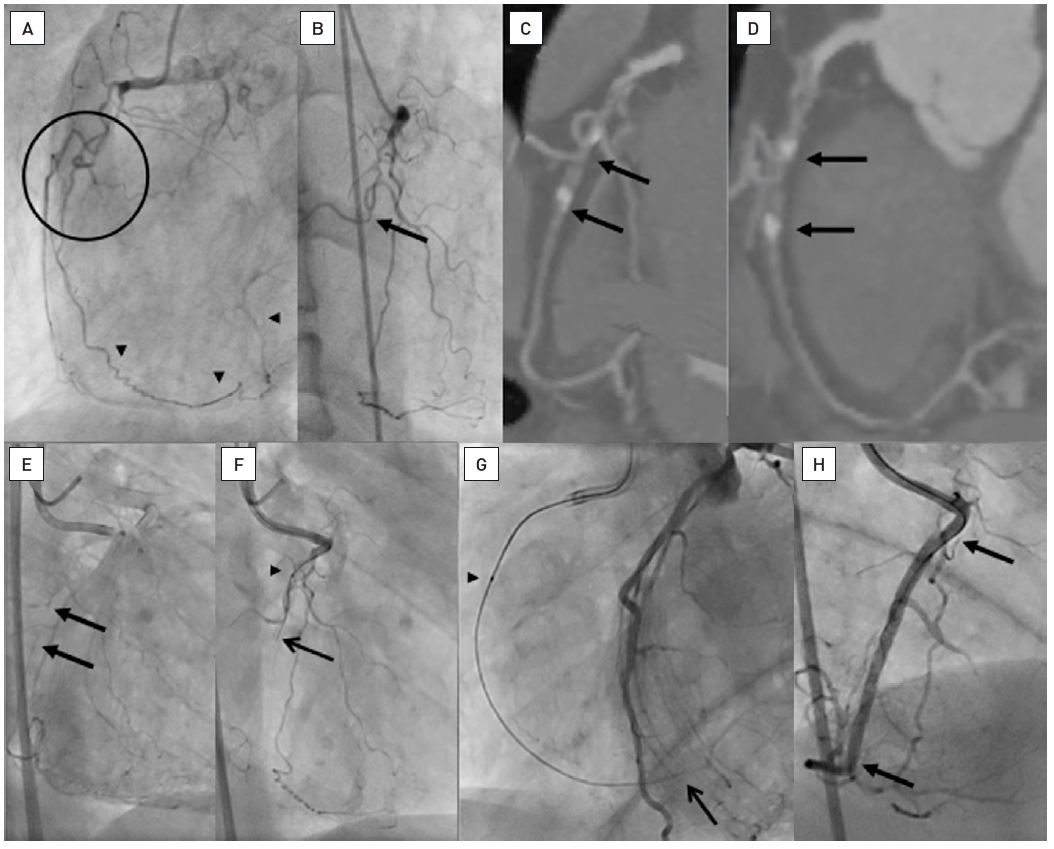
A: LAO view of a proximal RCA occlusion with several side branches obstructing the identification of the occlusion entry site (within circle). The distal PL system of the RCA is filled by an ipsilateral epicardial collateral (arrow heads). B. The RAO view with the side branches and a probable occlusion site at the take-off of a side branch (arrow). C and D. The multislice CT (MSCT) in both RAO and LAO representations reveal the occlusion site clearly identifying the occlusion between the side branch and the distal calcified spot (between arrows). E. The simultaneous injection of contrast form antegrade and contralateral identifies the site of occlusion with faint contrast filling at the end of a long filming sequence (between arrows), reassured by the MSCT. F. With the information of a short occlusion with entry without calcium, a Fielder XT (ASAHI Intecc) was chosen, supported by a Finecross microcatheter (Terumo) (arrow head). The wire successfully passes the side branch and enters the occlusion (arrow). G. Gradual advancement of the wire followed by the microcatheter (arrow head) leads to gaining the distal vascular bed, confirmed by contralateral contrast injection (arrow). H. Final result after placing two Everolimus-eluting stents (Xience V, Abbott Vascular) (between arrows).
An important question during PCI of a CTO is when to stop the procedure, often to opt for a subsequent second attempt or to consider the patient best treated by surgical revascularisation, especially when other non-occlusive lesions require further attention. A typical reason to stop the procedure is a severe dissection with loss of distal target visualisation because of a subintimal haematoma. A retrograde approach may still be possible, but generally a second attempt after resolution of the dissection will be the best approach. There is no systematic study on the time required for resolution of a dissection, it may happen as early as the next day, but for the sake of radiation and contrast safety, a longer delay is a wise decision.
The operator should always consider a second attempt as a possible option if severe dissections occur or obstruction of collateral flow to the distal target make the guidance of the wire impossible. The success rate of a second attempt, with the lessons learned during the first approach in mind, is very high in experienced hands. For the safety of the procedure, and above all to prevent radiation and contrast damage to the patient, the deferral of the procedure is a sound advice to consider. One needs to keep in mind regarding the radiation burden, the damage to skin can be accumulative and precautions need to be taken to avoid the sam entrance field for a future attempt.
The published data show no difference in the complication rates between occlusive and non-occlusive lesions, and this seems to hold true also for advanced techniques and new dedicated guidewires , , (Figure 41). In view of the often-disputed indication to re-canalise a CTO, and the viable option of surgical revascularisation, the interventional procedure must be kept a safe procedure. A careful risk assessment is mandatory before engaging a CTO in a certain patient. Risk scores such as the Progress Complication Risk score may be useful .
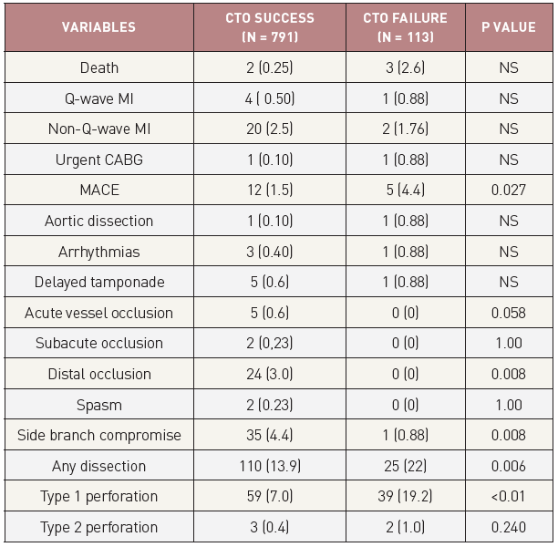
In-hospital outcomes and complications after PCI for CTO in successful and failed cases from the Toyohashi heart centre, Japan [from ]
Some complications are typical for a CTO procedure, such as perforating a vessel during wire advancement, but this is harmless as long as it is correctly recognised. Therefore, every care must be taken to recognise and correct false wire positions, and never to follow these wires with a balloon without absolute certainty of correct intraluminal wire position. Dissections and perforations may lead to contrast staining of the myocardium, which is not necessarily a reason to stop the procedure as long as it does not compromise the collateral vessel supply.
Pericardial tamponade is the feared acute complication, which occurs rarely when the above-mentioned rules are followed closely , . During the procedure all other anticoagulants except heparin (which can be readily reversed by protamine sulphate) should be avoided. However, in the case of heparin induced thrombocytopenia, the short-acting agent bivalirudin could be an alternative . There is no data to support the use of glycoprotein IIb/IIIa antagonists in CTOs.
In the situation of a wire perforation with the danger of pericardial tamponade the operator needs to be experienced in placing a pericardial drain if needed; often this can be avoided by rapidly obstructing the leakage with a balloon inflated for several (more than 10) minutes to seal the damage. If this does not work, negative pressure suction on a microcatheter advanced far into the distal vessel may help, or thrombus injection, coil placement or microspheres through this microcatheter. The problem will be difficult to control if the leakage is fed not only by the antegrade course, but also via collaterals. In this situation reversal of heparin anticoagulation with protamine sulphate and a pericardial drainage for some time may be the only option, and in the case of continuing effusion, a surgical repair.
Before PCI for a CTO is attempted, one needs to be familiar with at least with one, better several efficient techniques to deal with perforation (fat embolization, coil embolization, microsphere injection, thrombin injection) . Most important is to have the distal wire tip always in view, and to watch carefully for signs of perforation. Other complications which have been observed are damage inflicted on neighbouring vessels during the approach towards the occlusion. Here particular care is required as damage with partial vessel occlusion may put the patient at severe risk as one artery is already chronically occluded. Stiff wires should not be advanced through the left main artery across angles to avoid such damage, but rather they should be advanced through OTW catheters which are put into position with the help of regular floppy guidewires.
A major concern with the above-described complex procedural techniques is the infliction of radiation and contrast medium induced complications. Some of the risk can be reduced pre-emptively by realising the problem early on. Radiation safety is a part of interventional training, and it especially needs to be applied during procedures like CTO PCI. Limiting the field of view with collimation is most important, and extra effort should be made to adapt the field frequently during the procedure. During the course of the wire progress, the field needs to be adapted, later on during a procedure the field needs to include the position of the wire tip, and a larger field may be helpful. Filming should be limited to the minimum necessary for the wire progress, as it increases radiation dose by several factors as compared to fluoroscopy. Radiation will run typically into 40 to 60 min fluoroscopic time, sometimes even longer. To avoid radiation damage to the patient’s skin, collimation should be used whenever possible and the angulation must be changed and adjusted frequently to avoid a single spot radiation , . That these factors can be controlled and are mainly influenced by the operator was demonstrated in complex PCI and CTO procedures . The limiting factor in a procedure should not be the fluoroscopy time but the effective dose, and this can be influenced by the operator early on during the procedure. If the total radiation dose exceeds certain limits (e.g., 5 Gy) the patient needs to be advised and informed of possible delayed skin reactions, and further counselling should be arranged. Reporting of the radiation dose, either as effective patient dose (air Kerma in mGy) or dose area product (in cGycm2) or both, to the regulatory authorities is required in many countries. Modern X-ray equipment allows us to reduce radiation to levels that lie at a fraction of the doses reported in the early experience of complex CTO PCI . While the awareness of radiation risk is increasing among operators also in the interest of reducing the operator’s long-term exposure risks , , these new X-ray equipments are often not used to their maximum efficiency. When going into the further details of the radiation component, namely fluoroscopy and cine acquisition related dose, there are potentials for even further reducing the radiation exposure for the patient. In a recent study the critical threshold of 5Gy was never exceeded with a modified radiation protocol even in patients with high BMI, thus eliminating the concern for radiation risk as one of the reasons to terminate a procedure prematurely .
Like the radiation exposure, contrast usage is also greatly influenced by the operator. Limits of maximum contrast volume for each individual patient should be pre-specified according to the glomerular filtration rate (GFR) before the PCI. The maximum amount of contrast for each individual patient should be set before the start of the procedure with respect to the patient’s age and kidney function. A rule of thumb is to limit contrast to four times the GFR , . The contrast use can be reduced by using smaller guide catheters and diagnostic catheters for contralateral injections, and in critical patients this may be an indication to use the retrograde marker wire technique to avoid repetitive contrast injections during wire manipulation. As a precaution fluid hydration should be applied liberally before and during a CTO procedure. The indication for the retrograde approach may be based on the need for limited contrast use, as it requires less contrast once the wire is passed through the collateral channel. Furthermore, IVUS can be used from the time of balloon inflation to stent implantation to make any contrast injection unnecessary .
Nevertheless, certain patient groups are at increased risk of contrast-induced acute kidney injury and require specific precautions: elderly patients above the age of 75, diabetics, with low ejection fraction, and with pre-existing chronic kidney disease . A primarily retrograde procedure could be the solution to avoid renal impairment, that could be combined with IVUS even achieve a contrast-free procedure .
The advances of interventional therapy for CTOs over the past decade, and even since the first print edition of this chapter, are remarkable. The challenge for the experienced operator is now to choose the most appropriate strategy for each type of lesion. The ultimate goal should be to treat the patient successfully in one treatment session, and, thus, the goal is to achieve the success with the approach with the highest likelihood of success, and chose alternative strategies in case of failure of “plan A“ which have the highest additional likelihood of success. We need to limit the utilisation of cathlab resources, and cathlab time, as interventional devices to treat CTOs can be costly, and resources are limited.
The choice of primary and secondary strategy, and additional alternatives depends on the operator’s skill and familiarity with different approaches and devices (Figure 42). In the US the so called “hybrid approach” has been advertised as one that incorporates a liberal use of dissection-and-re-entry by the StingRay catheter in about one third of cases. In countries with less commercial penetration of this device the retrograde approach is favoured as an early alternative route in case of antegrade wire failure. Also, the use of IVUS as a tool to help redirect a wire from the subintimal path or even avoid such a route by identifying the proximal entry point will not be familiar to every operator.
There will not be a singular recipe to achieve a successful procedure, but it is of advantage to familiarise oneself with all possible alternative options and chose them early enough to revascularise the CTO successfully.
Advancements in the percutaneous revascularisation of a CTO, both in the primary procedural success and in the long-term vessel patency, have led to a change in our perspective of this specific complex coronary lesion subset. In recent guidelines the indication for PCI is identical to any other coronary lesion in stable angina pectoris, requiring certain symptoms or ischaemia. In addition, viability must be present for PCI in post-MI CTOs, which can be assessed by cardiac MRI. The improvement in procedural success is due to improved devices and modified techniques which need to be followed. The specific subtleties of these antegrade and retrograde techniques require further specialisation on the part of interventional cardiologists in order to obtain sufficient experience.
The treatment of a CTO is often called the last frontier of coronary interventions, implying that frontiers need to be explored and crossed. However, this must not lead to an irresponsible attitude towards the patient, and a competition among operators for the most daring technical approaches. The safety of the patient must the foremost priority of the operator, and PCI needs to be undertaken within the limits of this prerequisite. Any of these advanced techniques require familiarisation with all aspects of possible complications, and a continuous experience. Within each interventional programme, the treatment of complex CTOs should be restricted to one or two expert operators, and only those with a high workload should advance further to the more complex techniques of the retrograde approach. The retrograde approach to a CTO carries the risk of inflicting damage to the donor artery, and therefore should never be the principal routine approach. Following this recommendation, it will become possible to offer PCI as the principal revascularisation approach to a CTO, with a success rate close to the range achieved in non-occlusive lesions. as well as a continuous workload to achieve the highest possible success rate. Once the occlusion is crossed, new balloon and support devices facilitate lesion preparation for a subsequent and obligatory implantation of DES(s). The procedure is aided by additional imaging modalities like intravascular ultrasound and may also be facilitated by preprocedural MSCT. In the face of these advances, procedural safety needs to be the main objective. Since patients are treated for symptomatic relief, without evidence so far of a prognostic benefit as seen in most patients with stable angina pectoris, the complication rate must remain low and possible complications need to be managed by the operator without sequelae for the patient. After the success rate in CTOs has reached levels well beyond 90%, the focus in the future will be to maintain a durable result with the lowest possible rate of complications.
Masahisa Yamane, Kenya Nasu, Masaaki Okutsu, Makoto Sekiguchi
Updated on August 26, 2021
Emmanouil S. Brilakis, Lorenzo Azzalini, Dimitrios Karmpaliotis, William Nicholson, Stephane Rinfret
Updated on May 13, 2021